Problem 55-30
Source: Adapted from Problem 31 - RLC 2008 Problem List IV - Discipline
Electrical Circuits of the School of Engineering - UFRGS - 2008 - Prof. doctor Valner Brusamarello.
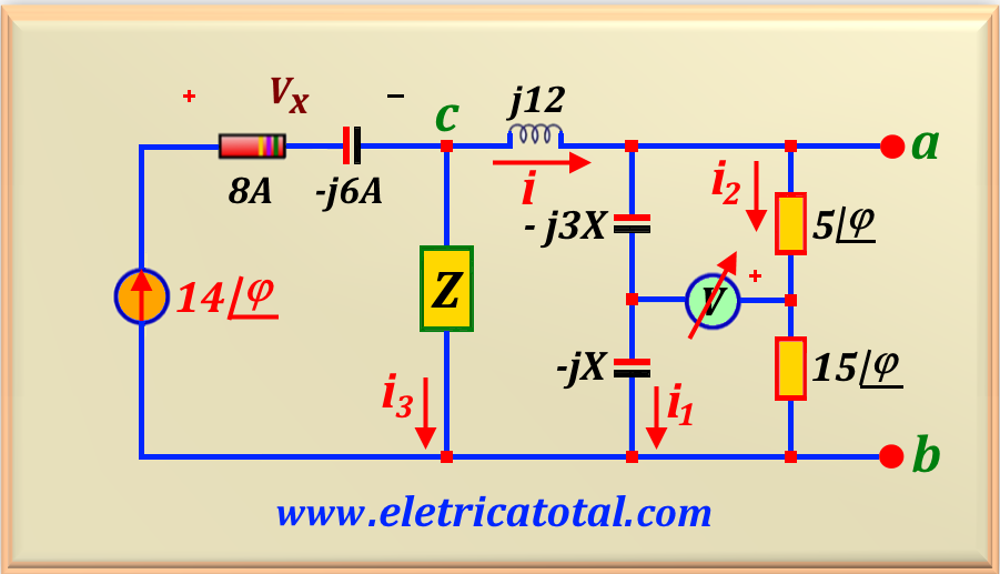
In the circuit shown in Figure 55-30.1, the voltmeter reading V is known to be 100 volts and
i = A∠φ. Furthermore, the voltage read by the voltmeter is
in phase with Vm. It is also known that φ = 36.87°. Find:
a) the values of i, i1 and i2;
b) the value of A and X;
c) the value of Z.
Figure 55-30.1
Solution of the Problem 55-30
Item a
Let's recall that an ideal voltmeter has infinite impedance. Taking this into account,
we can write the following circuit equations in the part where the voltmeter is connected.
j X i1 + 15 ∠ 36.87° i2 = 100
- j 3 X i1 - 5 ∠ 36.87° i2 = 100
An easy way to solve this system is to multiply the first equation by 3 and add the two together.
Thus, we get:
40 ∠36.87° i2 = 400
Performing the calculation, we find the value of i2, or:
i2 = 10 ∠-36.87° A
We can determine the phase of the value measured by the voltmeter by calculating the phase of
Vx, since the statement states that the phase of both is equal. Let's calculate the phase of Vx.
Vx = 14 ∠36.87° x 10 ∠-36.87° = 140 ∠0° V
Since we know the value of i2, we can determine the potential difference between the points a - b.
Vab = 10 ∠-36.87° x ( 5 ∠36.87° + 15 ∠36.87°) = 200 ∠0° V
Knowing the value of Vab, we can determine the phase of i1.
i1 = 200 ∠0° / - j 4 X = (50 / X ) ∠90°
eq. 55-30.1
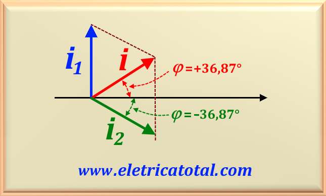
To find the value of i, we must use the information in the problem statement
which states that the angle of this current is 36.87°. Using this information along with
knowledge of the phase of i1 and the value of i2,
we can draw a graph that will help us determine the value of i, as shown in
Figura 55-30.2.
Figura 55-30.2
Note that the angles of i and i2, in magnitude, are absolutely equal. From this, it is easy to conclude
that the magnitudes of the currents are also equal. Then:
i = 10 ∠ 36.87° A
Using Kirchhoff's law for currents at node a, we obtain:
i = i1 + i2 ⇒ i1 = i - i2
So, replacing the variables with their respective numerical values and performing the calculation, we obtain:
i1 = 10∠36.87° - 10∠-36.87° = 12∠90° A
eq. 55-30.2
Item b
To find the value of A, simply compare i = A ∠ φ with the value of i. Thus, we easily conclude that:
A = 10
To find the value of X, let's compare eq. 55-30.1 with
eq. 55-30.2 and we easily find:
12 = 50 / X ⇒ X = 25 / 6 Ω
Item c
To calculate the value of Z, we will first calculate the value of i3,
the current that flows through Z as shown in the circuit in Figure 55-30.1. Using Kirchhoff's law for node c, we have:
i + i3 = 14 ∠36.87° ⇒ i3 = 14 ∠36.87° - 10∠36.87
Performing the calculation, we find:
i3 = 4 ∠36.87° A
Now we need to find the potential difference across Z. From the circuit, we have:
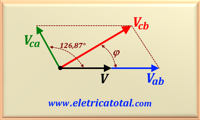
Vcb = Vab + Vca
Since we have already calculated the value of Vab, let's find the value of Vca. Therefore:
Vca = j 12 x i = 12∠90° x 10∠36.87° = 120∠126.87° V
Where we use the fact that j 12 = 12∠90°. With this data, we can plot a graph
of the voltage involved in the calculation as shown in Figura 55-30.3.
Figura 55-30.3
To calculate the value of Vcb we will use the law of cosines, as studied in chapter 51Phasors. We will use eq. 51-02 where, in this equation, x represents the voltage
Vcb.
Vcb2 = Vab2 +
Vca2 + 2 Vab Vca cos θ
Where θ = 126.87° represents the angle that the voltage Vca makes with Vab.
Making the numerical substitution in the equation above and performing the calculation, we find:
Vcb = 160∠36.87° V
Now that we know the voltage across Z and the current flowing through it, using Ohm's law we find its value, or: