So far we have studied that for direct current, power was nothing more than the product between the voltage
applied to the component by current flowing through it. Now, in the study of alternating current, we are
going to study various types of power.
Let's start with the so-called instantaneous power.
We have seen in the previous chapter that we can define an electric voltage or
an electric current by a sinusoidal or cosine function. These functions
vary in time, having maximum and minimum values. So let's define one function for the instantaneous voltage and another for the current
instantaneous.
v(t) = Vmax cos (ω t + θv )
i(t) = Imax cos (ω t + θi )
As we know, power is given by the product between voltage and current, hence:
p(t) = v(t) i(t) = Vmax Imax cos (ω t + θv ) cos (ω t + θi )
Note that we have the product of two sinusoidal functions. By the trigonometric properties
we can develop this product using:
cos A cos B = = 1/2 [cos (A - B) + cos (A + B)]
Applying this property we will find a function with two parts. The first part will be
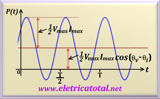
1/2 Vmax Imax cos (θv - θi ) . This part represents
a fixed value of the power, independent of time and its value depends on the phase difference between the voltage
and the current. In other words, it is the DC component of power.
The second part represents a time-varying value due to the cosine function that appears as
1/2 Vmax Imax cos (2 ω t + θv + θi ).
This cosine function has a frequency twice that of the voltage or current.
In the Figure 52-01 we show the graph of
the power function.
Figure 52-01
It should be noted that when P (t) is positive, the power is absorbed by the circuit. And
when P (t) is negative, power is absorbed by the source
(in this case we must have energy storage elements in the circuit such as capacitors and inductors).
In the technical literature, the maximum value of a function is also known as
PEAK value. If we want to express the difference between the maximum and minimum values,
we usually use the term value from PEAK to PEAK. For sines and cosines functions,
we have the following relation: Vpp = 2 Vp. For example,
if v = 5 sen(ωt) volts, then
Vmax = Vp = 5 volts and Vpp = 10 volts.
The unit of measurement of the instantaneous power is watt.
To talk about average power let's focus on the first part of instantaneous power, which is given by:
P = v i = 1/2 Vmax Imax cos (θv - θi )
Here we define the angle θ as the angle between the voltage and the current, that is:
θ = θv - θi
Power average or real power, as it is also known, is the power supplied to the load and dissipated by it.
Note that this power does not depend on the voltage being delayed or advanced in relation to the current.
Only the absolute value of the θ angle is of interest, since you should remember that
cos (- θ) = cos θ.
eq. 52-01
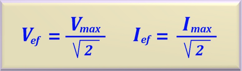
Intentionally, in the above equation, we write Vmax /√ 2 and
Imax /√ 2 to anticipate what we are going to consider in the next
item, the so-called effective value.
So far we have worked with maximum and minimum values of the functions they represent
voltage or current. But these values only happen in a certain time t. We are interested in a value that can represent these values at any time, as if it were a value in direct current. It is in this
moment we define the effective value or rms of an electric voltage or current.
Effective value, or as it is also known, value rms ( root mean
square), was defined as that equivalent sine value (or cosine) that when applied on a resistive load would dissipate the same power if the load were to be fed with a certain continuous value.
This equivalence of values is given by:
eq. 52-02
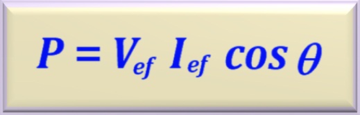
So we can redefine the average power, or also known as effective power, or
rms, or real power, with the effective values of the voltage and current, that is:
Let us analyze the case of providing mean power to the passive components that have been studied so far.
5.1. Power Absorbed by an Ideal Resistor
We know that a resistor does not cause a lag between the voltage and the current to which it is subjected.
Then θ = 0° e cos 0° = 1, resulting in that power is simply the
product between the voltage on the resistor and the current that circulates through it.
Example - We apply a voltage across a resistor
equal to v = 20 sen(ωt + 20°) and we obtain the current i = 4 sen(ωt + 20°).
What is the value of the resistance and what is the real power dissipated by it?
Solution - By the law of Ohm we have to
R = Vmax/Imax or R = 20 / 4 = 5 ohms. Very easy!
Now let's calculate the power that the resistor dissipates. Notice that as the voltage
and the current were given by a sine function, then the value that multiplies the sine function is the maximum value (or peak value) the voltage (or current)
reaches. Therefore, using the average (or real) power equation for resistors, we find:
P = (Vmax Imax) / 2 = (20 4) / 2 = 40 watts
5.2. Average Power in a Reactive Element
We know that in an ideal (or pure) inductor the current is delayed by 90 ° in relation to the voltage applied thereto.
For an ideal (or pure) capacitor the current is advanced 90 ° in relation to the voltage applied to it. Note that for any ideal reactive element that we consider there will be a 90 ° lag between voltage and current.
Now, if we have the angle θ = 90 ° then as cos 90 ° = 0, and by eq. 52-03
this means that the average or real power
in a reactive element is NULL.
Thus, in any network that has only inductors and / or capacitors at average power
will always be NULL.
In practice, since we do not work with ideal (or pure) components, any circuit will always contain some resistive
element associated with one or more reactive elements. This suggests that there will always be a lag between applied
voltage and electric current flowing through the circuit. This phase shift is known as POWER FACTOR and is defined as:
Power Factor = PF = cos θ
As we anticipate in item 3, we are only interested in the absolute of the angle
θ. Then a question arises: how do we know if the power factor is caused by
an inductive or capacitive circuit? It's simple: let's base ourselves on the characteristics of the elements.
So if the circuit is predominantly inductive, we say that the power factor is
INDUCTIVE or DELAYED ( because the inductor to delay the electric current in relation to the voltage).
If the circuit is predominantly capacitive, we say that the power factor is CAPACITIVE or ADVANTED (because the capacitor to advance the electric current in relation to the voltage).
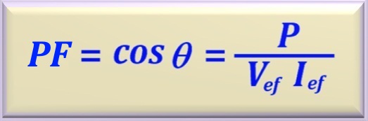
Another way of expressing the power factor is in function of the real power and the effective values (or rms) of voltage and current. See below how we can write:
eq. 52-04
Reasoning with Logic
We know that the cosine function is dimensionless. As in the numerator of the above equation we have the mean power, this suggests that the term in the denominator must also be a power. It's really,
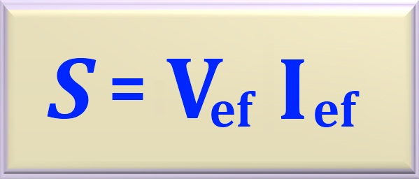
we call this term of APPARENT POWER and is usually represented by the letter S. Then we can write it as:
eq. 52-05
Note that for the computation of apparent power, the angle of lag between voltage and current is not relevant.
To avoid confusion with real power, the unit of measure of apparent power is
volt-ampère, or simply, VA.
In this way we can conclude that the apparent power will only equal real power when the circuit
presents a purely resistive total impedance, since in this case PF = 1 . Therefore, if there are reactive
elements in the circuit we have 0 < power factor <1 and the apparent power, in this case, it will
always be greater than the average power.
We can represent power as a complex magnitude. In this case, the complex power module represents the apparent power and the real part represents the average power or real. From the imaginary part, a new magnitude appears which we call REACTIVE POWER and its unit is
reactive volt-ampère, or simply VAr, and is usually symbolized by the letter Q.
Let us express the complex power as the product between the effective voltage (rms) and the
conjugated complex of the effective electric current (rms), or:
eq. 52-06
If we have the value of complex power and, moreover, we know the value of the angle of lag between voltage and current, then we can easily calculate the value of the real or average power using the equation below.
eq. 52-07
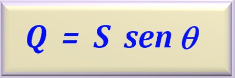
The same applies to reactive power, just replacing the cosine function with the
sine function as we can see in the equation below.
eq. 52-08
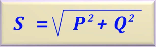
As the complex power, the real power or mean and the reactive power make
part of a rectangle triangle (as we'll see in the next item), then using the
theorem of Pythagoras we find a relation between the three magnitudes.
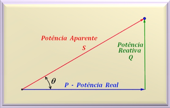
Looking closely at the last equation of the previous item it is clear that we can represent
the complex power by a right triangle where each side will be interpreted as a
power. The real power will be represented by the adjacent side, the
reactive power will be represented by the opposite side, and finally
apparent power will be represented by the hypotenuse of the rectangle triangle.
In the Figure 52-02 we can see the representation of the three powers in a triangle.
Figure 52-02
Attention
We must emphasize that in Figure 52-02 we use the fact that the
reactive power is positive, that is, inductive. That is why we represent the
reactive power above the horizontal axis. In the technical literature, there are
some authors (eg Joseph A. Edminister) who prefer to use the fact that the inductor
delays the electric current in relation to the voltage. In this case, they invert
the direction of the triangle, representing the inductive reactive power down.
They take into account the fact that the angle is negative.
Thus, the capacitive reactive power is oriented upwards. However, it should be noted that in any case,
the same power and angle results will be obtained.
Therefore, the student can choose how to draw the power triangle: if from the point of view of the angle
(negative for inductive reactance and positive for capacitive reactance) or if from the power point of
view (positive for inductive reactance and negative for capacitive reactance).
Now that we have studied the various powers involved in AC circuits, we can study in more detail what is
power factor and why should we correct it.
As we have already seen, power factor is nothing more than the cosine of the phase angle between voltage and current. But ... why is this important?
The important fact to note is that large consumers, like industries, use many powerful electric motors and, as we know, electric motors are typically inductive circuits. In other words, they cause a large diferent of phase between the voltage and the electric current. How the company
the power supplier can only rate real power, so if we have a high power reactive power circuit the company is experiencing a loss.
For this do not occur, by law, there are rules that establishment a minimum power factor for industries can operate.
In Brazil, this power factor can not be less than 0.92. The power company monitors every 15 minutes the power factor
of each consumer who is your customer. If the power factor of the consumer is below the value 0.92, as penalty,
it will suffer an increase in the charging.
For this reason the industries have a computerized system that constantly monitors
the power factor and, if it is found that it is out of regulation the computer automatically corrects the power factor.
The question we should ask is: HOW TO CORRECT THE PF ?
The answer is simple: just add "something" that reduced the electrical current lag in relation to the voltage.
The only component we have studied that allows this to happen is ... CAPACITOR. But ... add in what way? Large
consumers use capacitor banks that are connected in parallel with the load. Thus, by connecting and disabling the capacitor bank in parallel with the load, the system ensures that the power factor will always be between 0.92 and 1, and immune to sanctions.
The Problem 52-8 illustrates this power factor correction technique. To access it
click here!
In Chapter 7, we studied this theorem when we had only resistances in a DC-fed circuit.
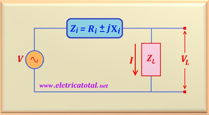
Now we are going to study it when in an AC-fed circuit and there is presence of reactive elements. Therefore, we will use as reference the circuit shown in the figure below.
Figure 52-03
The circuit presents a complex impedance (Zi) of fixed value, in series with a voltage source (V), and this system feeds a load also complex (ZL).
In relation to the power in alternating current we can establish three cases that can occur. Let's go
analyze them separately.
Case 1
Let's look at the case when the load is made up of only one resistor. In this case, we have
XL = 0. Thus, the maximum power transfer to
the resistive load occurs when the following condition is satisfied:
RL = |Zi| = √(Ri2 + Xi2)
eq. 52-10
Therefore, there will be maximum power transfer to the load when it is equal
to the absolute value of the complex impedance, Zi.
If the reactive element of the series impedance is null, that is, Xi = 0,
then we fall back in the case that we studied in chapter 5, that is,
RL = Ri .
Case 2
In the second case, we will consider the load with fixed resistive element and
reactive variable.
Thus, we have to satisfy two conditions so that there is maximum power transfer
for the load. See below:
RL = RiandXL = - Xi
eq. 52-11
This means that we must have a relationship between ZL and Zi,
such that one is the conjugate complex of the other. In other words: if the load is an inductive circuit ,
then Zi must be a capacitive circuit.
And vice versa.
Caso 3
In the third case, we will consider the load with resistive variable element and
fixed reactive.
Thus, for maximum power transfer to the load, we have to satisfy the following condition:
RL = √[Ri2 + ( Xi + XL)2]
= |Zi + jXL|
eq. 52-12
Realize, once again, that XL = - Xi, so we relapse into
case 1, where RL = Ri, condition that there be maximum
transfer of power.
Attention
If you are interested in the mathematical proof of these three cases you can obtain
click here!
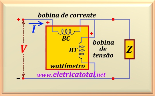
A wattmeter is a device that has the purpose of measuring active or real power.
Basically it consists of two coils, one to measure the electric current that flows through the load and the other to measure the voltage over the load. The first is a coil of very low ohmic resistance that is connected in series with the load. Ideally the voltage drop on it is NULL. Known as
current coil (BC).
The second coil has a very high ohmic resistance and is connected in parallel with the load .. Ideally
the current flowing through it is NULL. Known as voltage coil (BT).
In the Figura 52-03 we see the basic schematic of a wattmeter.
Figura 52-03
It has been agreed that if the current enters the positive terminal on the current coil and the voltage is positive at the
positive terminal on the voltage coil, then the wattmeter reading will be
positive, ie the load is consuming power. Thus, the real part of
the product between the voltage modulus and the modulus of the current measured by
the current coils will be the average power (or active, real), having as unit of
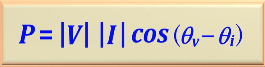
measurement the watt or kilowatt. Therefore the equation that we will
use to calculate the power will be:
eq. 52-13
Example
Let us use as an example the problem 54-6, whose solution
click here!
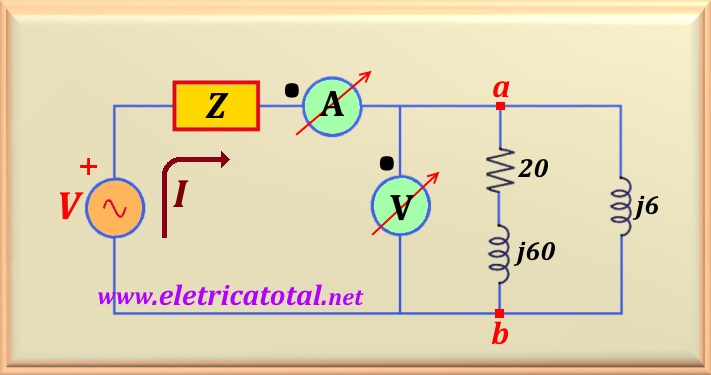
Let us consider the circuit delimited by points a-b as a load. Reviewing the
solution we know that
Vab = 50∠0° and that I = 9.09∠-88.42°.
Thus, these data are the values that the voltmeter and the ammeter
(representing the wattmeter), shown in the Figura 52-04, would read. Therefore,
from these values we find that the angle between the voltage at points a-b
and the current is θ = 88.42°.
Do not forget that cos (-88,42°) = cos 88.42°.
Figura 52-04
We can calculate the power consumed by the load using the equation 52-13, where we have to
θ = θv - θi , that is:
P = |V| |I| cos (θ) = 50 x 9.09 x cos (88.42°)
Performing the calculation, we find:
P = 12.53 watts
Since the load has only one resistor, then that power is all dissipated in the resistor
of 20 ohms, since inductors do not consume average power.