An LC circuit can be formed from an RLC circuit as long as the
resistor is eliminated from the circuit. As in an RLC circuit,
we can have an LC circuit in series or in parallel.
Let us first recall that the capacitive reactance is represented, in complex form,
as - j XC and the inductive reactance as + j XL.
Therefore, if these components are in series, the equivalent reactance will be the algebraic
sum of the two reactances.
In this case, we easily perceive that XL > XC, we will get an inductive circuit. Otherwise, that is,
XC > XL then we will have a capacitive circuit.
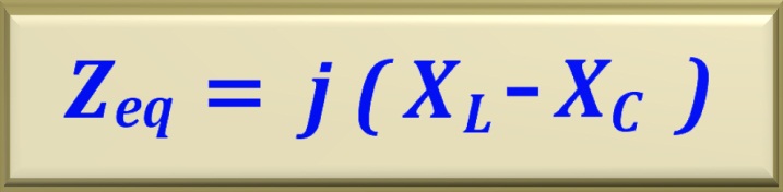
Taking this into account, the equivalent impedance of a series LC circuit can be written as:
eq. 56-01
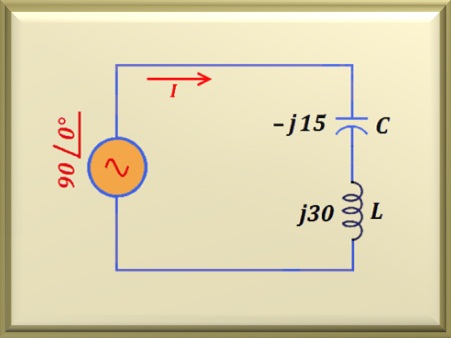
Figure 56-01
In the Figure 56-01 we see a circuit LC series. The values of the supplied components allow to determine if
the circuit is inductive
or capacitive. As the voltage on the capacitor will be 90° delayed in relation to the current and the voltage
on the inductor will be 90° advanced in relation to the same current, we conclude
that the voltages on the capacitor and on the inductor will be out of phase by 180°.
Let us write the equivalent impedance value in the rectangular form obeying the equation shown above.
Zeq = j (30 - 15) = + j15 Ω
In the polar form we have:
Zeq = 15 ∠ +90° Ω
Now that we know the equivalent impedance value, we can calculate the value of the
current flowing through the circuit. So:
I = V / Zeq = 90 ∠ 0° / 15 ∠ +90° A
Performing the calculation we find:
I = = 6 ∠ -90° A
Note that the angle - 90° is due to fact that the current is delayed in relation to the voltage
V. As we all know, delayed current means that the circuit has inductive predominance.
With the value of the current we can calculate the values of
VL and VC.
VL = XL I = 30 ∠ +90 x 6 ∠ -90° V
Notice that we have transformed j 30 into 30 ∠ +90°. Performing the calculation, we find:
VL = 180 ∠ 0° V
For the calculation of the voltage on the capacitor we have:
VC = XC I = 15 ∠ -90 x 6 ∠ -90° V
Notice that we have transformed -j 15 into 15 ∠ -90°. Performing the calculation, we find:
VC = 90 ∠ -180° V
Note that VL + VC is exactly the source voltage that powers the circuit,
that is, 180 ∠0° + 90 ∠ -180° = 90 ∠ 0°. In other words, it obeys the
Kirchhoff's Law.
If the inductive reactance is exactly equal to the capacitive reactance they cancel out, and the
equivalent impedance will simply be a short circuit.
This feature is extremely important when dealing with circuits and we want to eliminate (or at least drastically reduce) a certain frequency. We just have to choose appropriate values for L and C. Making equal XC and XL
and algebraically working the equality, we find the equation that relates the three variables.
Below, we show the final equation.
eq. 56-02
Using L in henry and C in farad we get f in hertz.
The circuit shown in the figure above (often in the technical literature, called "trap") is widely used in the radio frequency, with the purpose of eliminating undesirable frequencies for the smooth operation of the circuit as a whole.
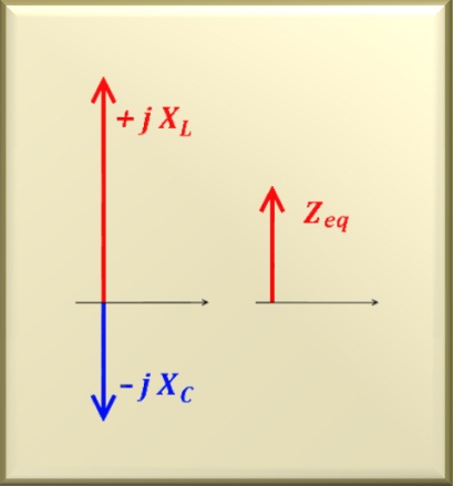
See the Figure 56-02 for the representation of the impedances involved in the
problem. On the left side, pointing up (red color) we have the inductive
reactance. Pointing down (blue color) we have the
capacitive reactance. These two quantities are on the imaginary axis.
On the right side, on the vertical (imaginary) axis we have the result
XL - XC, represented by Zeq, pointing
up because XL > XC.
Otherwise, it would point down.
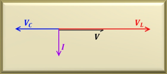
See the Figure 56-03 for the representation of the voltages involved in the
problem. We have the voltage on the inductor (red color) horizontally (0 °) and the voltage on the capacitor (blue color) horizontally pointing to the left (180 °) . The result of the phasor sum of the two voltages is
V (in black) pointing right horizontally (0°).
Note that current I is delayed by 90° in relation to VL and advanced 90° in relation to VC .
In this circuit it is clear that circuits containing only reactive elements do not dissipate power
average or real, since there is a 90° lag between V and I. Thus, in this case, a mean power NULL results, since P = V I cos 90° = 0 watts, because cos 90° = 0.
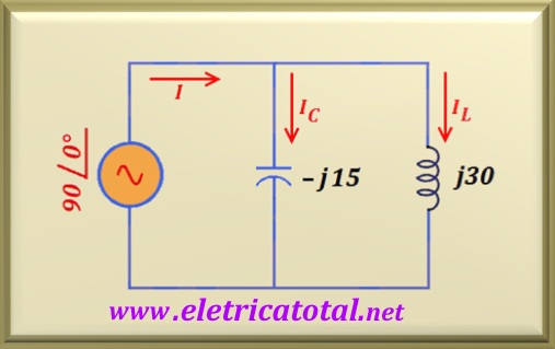
Let's form a parallel circuit with the same components used in the previous item.
In this case, the voltage on both the inductor and on the capacitor is the same.
Figure 56-04
See in the Figure 56-04 how the circuit with the components in parallel was.
We know that the current in the inductor (IL) will be delayed 90° in relation to the voltage and the current in the capacitor (IC) advanced 90° in relation to the same voltage. Then, the current (I) that will be supplied by the voltage source will be the phasor sum of the two.
As previously stated, we can use the same principles studied for DC to calculate the equivalent impedance. Thus, we assume the reactance as a resistance and perform the calculation as if they were two resistors in parallel. Do not forget that the reactance is a complex number. Then we can write:
Zeq = XC XL / (XC + XL )
Zeq = 15 ∠ -90° x 30 ∠ +90° / - j15 + j30
Notice that we have transformed - j15 into 15 ∠-90° and also
+ j30 into 30 ∠+90° in the equation above. Of course, in the denominator,
- j15 + j30 = +j15 = 15 ∠+90°. Then:
Zeq = 450 / 15 ∠ +90°
By performing the calculation, for the equivalent impedance we find:
Zeq = 30 ∠ -90° = - j30 Ω
Note that when we put the components in parallel, the equivalent impedance (in this case)
is a capacitor which has an impedance of 30 ohms.
Let's calculate the currents in the circuit.
IL = V / XL = 90 ∠0° / 30 ∠+90° = 3 ∠-90° = - j3 A
IC = V / XC = 90 ∠0° / 15 ∠-90° = 6 ∠+90° = j6 A
We can calculate the value of the current I that circulates through the voltage source making the phasor sum of IC and IL or using the Ohm's law.
We will do it both ways.
We would like to point out that the LC circuit, both the series and the parallel
circuit, the frequency at which the two operate is given by the equation already
seen above and we will repeat here
for clarity.
eq. 56-02
Then, notice that by varying the value of L and/or the value of C, we are also
changing the frequency at which the circuit operates. This feature makes the parallel LC circuit widely used in oscillators and RF tuners (such as AM, FM, TV, etc. ..),
because by varying L or C we will be varying the tuning frequency and, consequently,
selecting the broadcaster or signal in which we are interested.