In a synchronous generator we have two types of windings, commonly known as:
Field Winding
Armature Winding
In general, the expression field windings is applied to the windings that produce the field
main magnetic of the machine and the expression armature windings is applied
to the windings in which the main voltage is induced. On synchronous machines,
the field windings are on the rotor, so the expressions windings
rotor and field windings are used in the same sense. Similarly, the
expressions stator windings and armature windings are
also used in the same sense.
In the project
of the rotor, to obtain this magnetic field, you can choose to use a permanent magnet or a
electromagnet, obtained by applying a DC current to a winding
of this rotor. The generator rotor is then driven by a prime mover,
which produces a rotating magnetic field inside the machine. this magnetic field
The rotating rotor induces a set of three-phase voltages in the stator windings of the generator.
The rotor of a synchronous generator is essentially a large electromagnet. The poles
rotor magnets can be constructed in two ways:
Salient-pole - it is a pole that protrudes radially from the rotor.
Non Salient-pole -it is a magnetic pole with the windings fitted and flush
with the rotor surface.
Non salient pole rotors are commonly used in two and four pole rotors,
whereas salient pole rotors are normally used in rotors of four or
more poles.
As the rotor is subject to changing magnetic fields, it is constructed with
thin blades to reduce eddy current losses.
If the rotor is an electromagnet, a DC current must be supplied to the circuit
of field of this rotor. As it is rotating, a special arrangement will be required
to carry DC power to its field windings. There are two common approaches to
supply the DC power:
From an external DC source that supplies DC power to the rotor via
of brushes and collector (or slip) rings.
Or supply DC power from a special DC power source mounted
directly on the shaft of the synchronous generator.
Slip rings are metal rings that completely surround the shaft of a
machine, but are isolated from it. Each end of the rotor DC winding is connected to a
of the two slip rings on the machine shaft
synchronous and a stationary brush is in contact with each slip ring. If the positive terminal of
a DC voltage source is connected to a
brush and the negative terminal is connected to the other, then the same DC voltage will be
continuously applied to the field winding, regardless of position
angular or rotor speed.
For small synchronous machines, due to cost, slip rings are used
and brushes to supply energy to the field winding in the rotor.
In larger generators and motors, brushless exciters are used
to supply the DC field current to the machine. A brushless exciter is
a small AC generator with its field circuit mounted in the stator and its
armature mounted on the rotor shaft. The exciter generator's three-phase output
is converted into direct current by means of a three-phase rectifier circuit that
it is also mounted on the generator shaft. This direct current then feeds
the field main DC circuit. Controlling low generator DC field current
of the exciter (located in the stator), it is possible to adjust the field current in
main machine without using brushes or slip rings.
To make the excitation of a generator completely independent of any external power sources, a small pilot exciter is
often used included in the system. A pilot exciter is a small AC generator with permanent magnets mounted on the rotor shaft
and a three-phase winding on the stator. It produces the power for the exciter field circuit, which in turn controls the
main machine field circuit. If a pilot exciter is included in the axis
generator, no external electrical power will be required to run the
generator.
Synchronous generators are by definition synchronous, meaning that the frequency
electrical energy produced is synchronized with or linked to the mechanical speed of rotation
from the generator. The field rotation rate
magnetic elements of the machine is related to the electrical frequency of the stator by
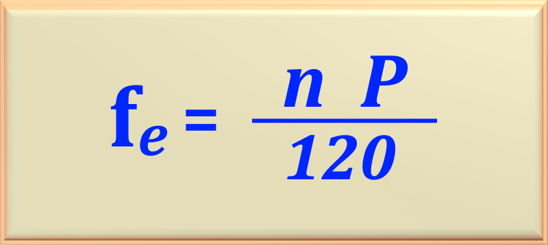
middle of eq. 105-01:
eq. 105-01
Where the variables are:
fe - electrical frequency, in Hz.
n - mechanical speed of the magnetic field, in rpm.
P - number of machine poles.
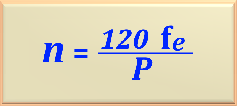
On the other hand, if we know the electrical frequency fe, we can calculate which one should
be the speed of rotation of the synchronous machine just working algebraically to eq. 105-01 and
getting the eq. 105-02, that is:
eq. 105-02
Since the rotor rotates with the same speed as the magnetic field, this equation
relates the electrical frequency to the resulting rotor rotation speed.
The generator must rotate at a fixed speed depending on the number of poles. So,
to generate power at 60 Hz in a 4 pole machine, it must turn the
1,800 rpm.
In chapter 75 we studied how we can obtain an induced voltage in a loop (Click here!). It was also seen that the eq. 75-12 defined the voltage induced in a loop. Whereas the
magnetic flux can be of the form Φ = Φmax sin ω t, then based on eq. 75-12
we can write that:
εind = Φmaxω cos ω t
This value is valid for a single loop. As the armature winding has N turns, then the voltage value
induced in the entire winding is given by:
εind = Φmax N ω cos ω t
After these considerations and assuming a three-phase synchronous machine, we can find the peak value of the induced voltage at
any of the phases simply using the above equation for its maximum value, that is, when ω t = 0. So:
EAmax = Φmax N ω
However, as we know, ω = 2 πf. So you can write:
eq. 105-2a
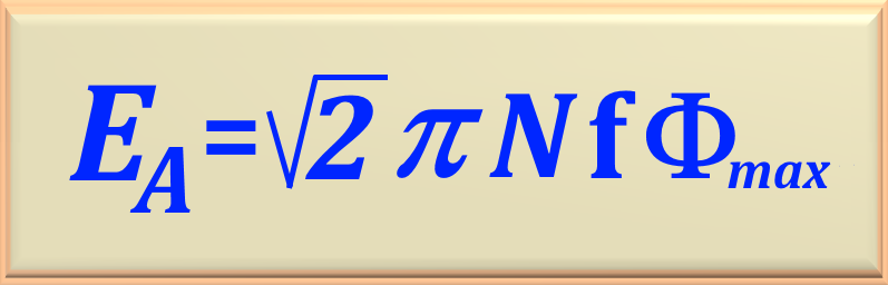
Therefore, it is possible to determine the effective value or RMS of the voltage induced in any of the phases of the machine, dividing the value found by √2, obtaining the eq. 105-03, or:
eq. 105-03
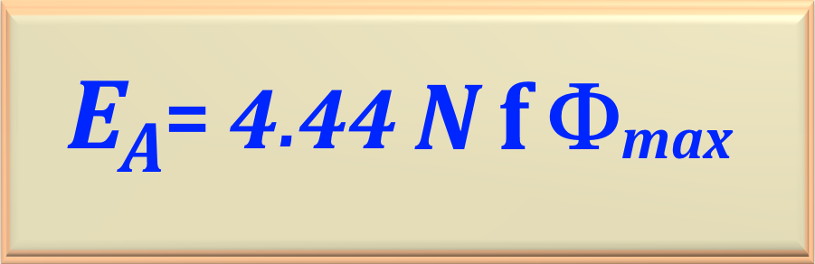
In the technical literature the eq. 105-03 is best known for the format of the eq. 105-3a where the product was made
√2 π.
eq. 105-3a
The effective voltage at the machine terminals will depend on whether the stator is connected in Y or
in delta. If the machine is connected in Y, the voltage at the terminals will be √3 EA. If
the machine is connected in delta, the voltage at the terminals will simply be equal to EA.
From eq. 105-03 it is possible to take the following conclusions:
The effective value of voltages at the machine terminals is proportional to the number of turns,
the intensity of the magnetic induction field and the speed of rotation of the machine.
For the frequency to be constant, the rotor speed must be
constant.
Keeping the speed constant, the effective value of the voltages can be modified through
of the variation of the inductor field.
We will develop an equivalent electrical circuit model that we will use to study the behavior
synchronous machine performance with sufficient accuracy.
The current IF flowing through the field winding produces a
flow ΦF in the air gap. On the other hand, the armature current
Ia flowing through the stator winding produces a flux Φa.
Part of this flux interacts only with the stator winding and is called leakage flux,
which we will call Φal. This flow does not interact with the flow due to
to the field winding. Therefore, most of the flux due to armature current is confined
in the air gap and strongly interacts with the flux field. This flow is called
armature reaction flow and is represented by Φar. Soon, the
resulting flux in the air gap, called Φr, is due to the components
of the two flows ΦF and Φar. Every flows
of these induce a voltage component in the stator winding. So,
EA is induced by ΦF, Ea is
induced by Φar and the resulting voltage Er is
induced by Φr. The voltage EA can be calculated
from the machine's open circuit curves.
It should be noted that the voltage Eair, known as
armature reaction voltage depends on Φar and therefore
this depends on Ia. From what has been exposed so far, we can write that:
Er = Ear + EA
Algebraically working this equation, we can write:
EA = - Ear + Er
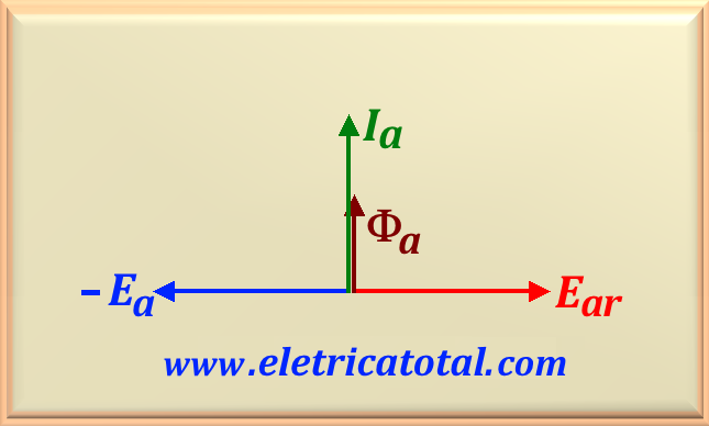
Thus, we can draw a diagram showing the phasors involved in this analysis.
Figure 105-01
From the diagram shown in Figure 105-01, we see that the flow Φar,
as well as the current Ia that generates it, are ahead of 90° in relation to the
voltage Ear. And in turn, the voltage - Ear is ahead
of 90° in relation to Ia. Remembering that an inductive reactance delays
the current at 90° with respect to the voltage, so this suggests that - Eair is
the voltage drop over an inductive reactance, which we will call Xar,
due to the current Ia. Using this fact, we can rewrite the last
equation as follows:
EA = j Xar Ia + Er
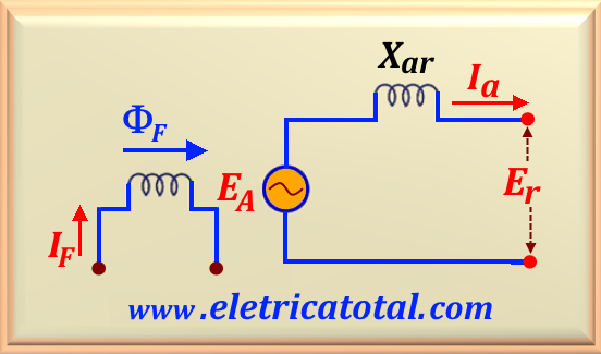
The Xar reactance is known as the armature reaction reactance or
magnetizing reactance and is shown in Figure 105-02.
Figure 105-02
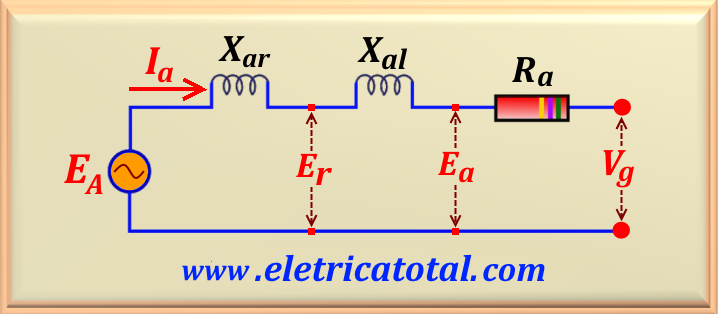
If the stator winding resistance Ra and the leakage reactance
Xal
(which takes into account the dispersion flux Φal) are included, the circuit
equivalent per phase is represented in Figure 105-03.
Figure 105-03
The resistance Ra is the effective resistance and is
approximately 1.6 times the dc resistance of the stator winding. The effective resistance
includes the effects of operating temperature and the surface effect caused by switching the
current flowing through the armature winding.
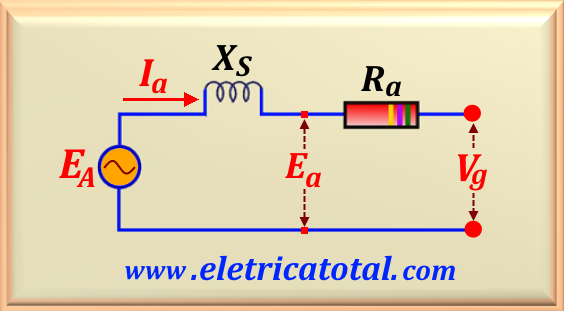
For simplicity, it is common to define a new reactance called the synchronous reactance and
represented by XS, which is
the sum of the reactances Xar and Xal. So, using this new reactance,
we can represent the synchronous machine model by the circuit shown in Figure 105-04.
Figure 105-04
Thus, we can define the following equations:
XS = Xar + Xal
ZS = Ra + j XS
It should be noted that the synchronous reactance XS takes into account all fluxes,
the magnetizing, as well as the dispersion, produced by the armature current.
The machine parameter values depend on the machine size. Table 105-01 shows
its order of magnitude. The units are in p.u.. An impedance of 0.1 pu
means that if rated current flows, the impedance will produce a voltage drop of
0.1 (or 10%) of the face value. In general, as machine size increases,
the resistance per unit decreases but the
synchronous reactance per unit increases.
Table 105-01
Small Machines (dozens of KVA)
Big Machines (dozens of MVA)
Ra
0.05 - 0.02
0.01 - 0.005
Xal
0.05 - 0.08
0.1 - 0.15
XS
0.5 - 0.8
1.0 - 1.5
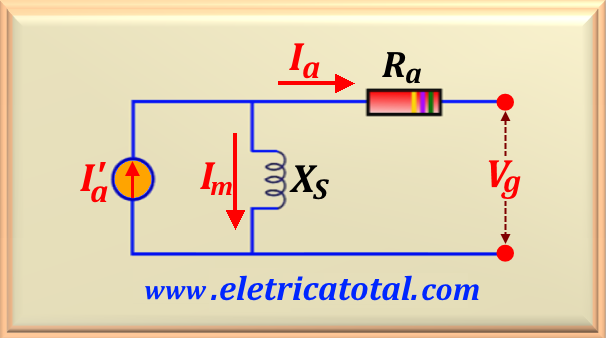
An alternative way of showing the synchronous machine equivalent circuit is to use
the Norton equivalent of the excitation voltage Ef and the synchronous reactance XS,
as shown in Figure 105-05.
Figure 105-05
Transforming to the Norton equivalent, we get:
I'a = EA / XS
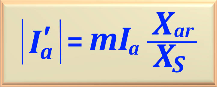
Doing some algebraic transformations it is possible to demonstrate that we can obtain the following relation:
eq. 105-04
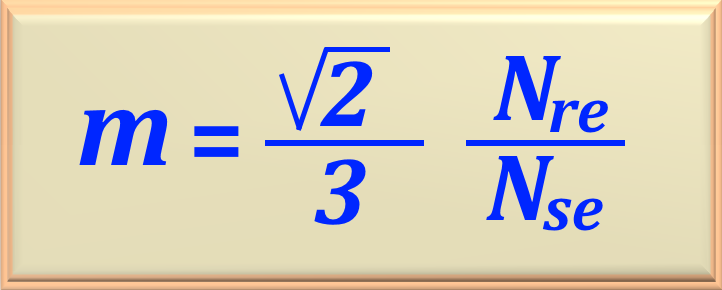
Where we define m as:
eq. 105-05
Where the variables are defined as:
Nre - is the number of effective turns of the field winding.
Nse - is the number of effective turns of the stator winding per phase.
Since the voltages of a synchronous generator are AC voltages, they are usually expressed as phasors,
which have magnitude and angle. Therefore, the relationships between them can be expressed by a graph
two-dimensional. When the voltages on one phase (EA, Vg,
j XS Ia and Ra Ia )
and the current Ia of this phase are plotted, resulting in a graph called
phasor diagram showing the relationships between these quantities.
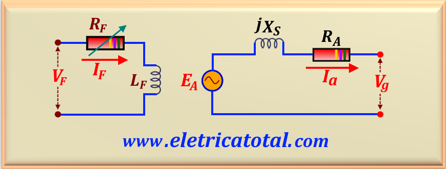
Figure 105-06
The Figure 105-06 shows the phase-by-phase equivalent electrical circuit model of a synchronous generator.
Note that the internal resistance of the field circuit has been incorporated into the variable external resistance,
resulting in a single resistance, designated RF. Based on this model, we will analyze the behavior of the generator
when connected to three different types of loads: resistive, inductive, and capacitive.
It should be noted that the circuit shown in Figure 105-06 presents a direct current voltage source, VF,
which powers the rotor field circuit, modeled by the
inductance and series resistance of the field coil. In series with the resistance RF
is an adjustable resistor (not shown in the circuit) that controls the flow of field current.
To represent the three-phase system, there are three circuits identical to the one shown, one for each phase.
The voltages and currents generated by them are identical in magnitude, but are out of phase with each other 120°.
These three phases can be connected in a delta or star configuration.
When using the phase-by-phase equivalent circuit, one important fact must be kept in mind: the three phases exhibit the same voltages and currents
only when the loads connected to them are balanced. If
the generator loads are not balanced, then more sophisticated analysis techniques
will be required. These techniques are beyond the scope of this website.
When we connect a resistive load to the generator, we know that the load has a power factor unity. In other words,
there is no phase shift between the terminal voltage, Vg, and the armature current Ia. Therefore,
we have φ = 0°.
Let's use this model to create the phasor diagram
shown in Figure 105-07, when we use a resistive load and, therefore, have a unity power factor.
Figura 105-07
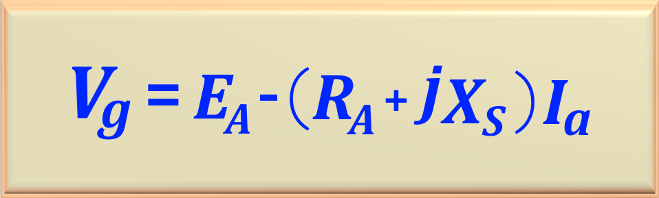
From the circuit shown in Figure 105-06, we see that the difference between the total voltage
EA and the phase terminal voltage, Vg,
is given by the resistive and inductive voltage drops. All voltages and currents are referenced to
Vg, whose angle is arbitrarily assumed to be 0°. Therefore, we can write the
equation that defines the terminal voltage Vg given by eq. 105-06, or:
eq. 105-06
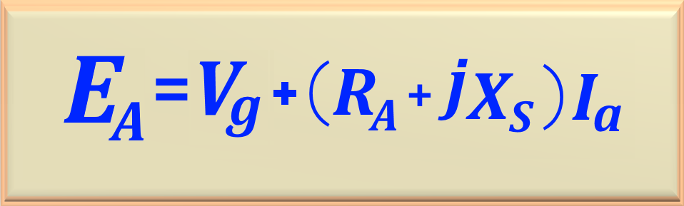
When solving some problems, we need to calculate the value of EA,
since we know the value of the terminal voltage, Vg. From eq. 105-06,
we can write eq. 105-06.1, below.
eq. 105-06.1
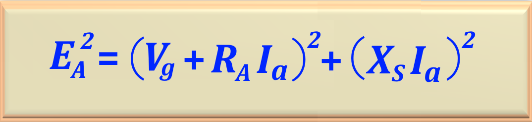
Optionally, we can write this equation in non-complex form, using the Pythagorean theorem
applied to the phasor diagram shown in Figure 105-07. See eq. 105-06.2 below.
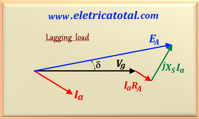
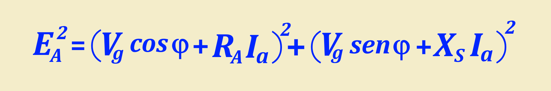
In the case of an inductive load, we know that the armature current Ia will lag behind the terminal voltage Vg.
The phasor diagram for this situation is shown in Figure 105-8 below.
Figura 105-08
From this phasor diagram, we can determine the value of the generator's internal voltage EMF, EA,
using the Pythagorean theorem.
To do this, we take the current Ia as a reference and easily arrive at eq. 105-07.1, shown below.
eq. 105-07.1
From this equation, it is possible to conclude that:
"For a given terminal voltage and armature current, a larger internal voltage EA is required for lagging loads."
Therefore, when you want
to obtain the same terminal voltage as in the case FP = 1, a larger field current will be required for
the lagging loads.
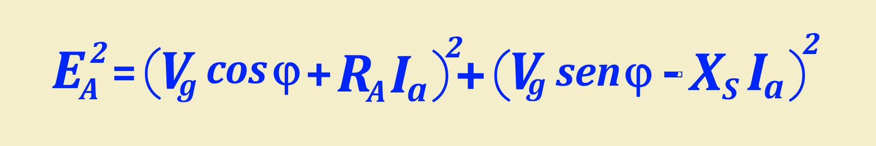
In the case of a capacitive load, we know that the armature current, Ia, will lead the terminal voltage,
Vg. The phasor diagram for this situation is shown in Figure 105-09 below.
Figura 105-09
From this phasor diagram, we can determine the value of the generator's internal voltage EMF,
EA, using the Pythagorean theorem.
To do this, we take the current Ia as a reference and easily arrive at eq. 105-07.2, shown below.
eq. 105-07.2
From this equation, it is possible to conclude that:
"For a given terminal voltage and armature current, a smaller internal voltage EA is required for the
leading loads."
Therefore, when you want
to obtain the same terminal voltage as in the FP = 1 case, a smaller field current will be required for
the leading loads.
A synchronous generator converts mechanical power into three-phase electrical power. The power source
mechanical, the prime mover, can be a diesel engine, a steam turbine, a hydraulic turbine
or any similar device. Whatever the source, it must have the property
basic assumption that its speed is almost constant regardless of the power demanded.
Otherwise, the frequency of the resulting power system would vary.
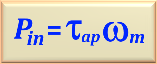
Not all the mechanical power that enters a synchronous generator becomes electrical power at the output
of the machine. The difference between the input power and the
output represents the machine losses. The input mechanical power is the
power on the generator shaft given by the product between the torque applied by the driving machine and
the rotational speed of the machine, that is:
eq. 105-07
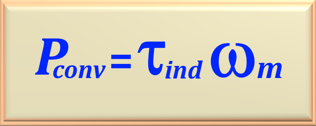
On the other hand, the power internally converted by the synchronous generator from the mechanical form to the
electrical form is given by the product of the induced torque and the machine rotational speed, or
it is:
eq. 105-08
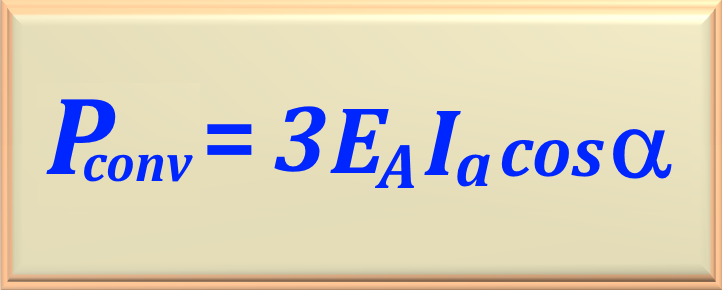
An alternative way of writing this equation is as eq. 105-09.
eq. 105-09
In this equation the angle α is the angle between the induced voltage EA
and the armature current Ia. The difference between the input power of the generator
and the power converted into it represents the mechanical, core and supplementary losses of the machine.
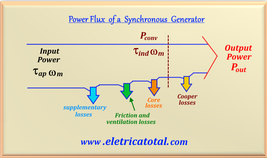
In Figure 105-10 we present a schematic showing the power flow in a synchronous machine.
Figure 105-10
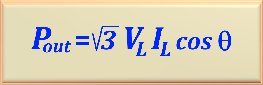
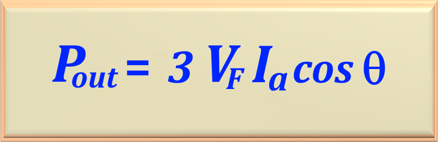
The effective electrical power that appears at the output of the synchronous machine can be expressed in line quantities
by eq. 105-10.
eq. 105-10
And in phase quantities by eq. 105-11, where we made Vg = VF
to emphasize the phase greatness.
eq. 105-11
We emphasize that, in this case, the angle θ is the angle between the phase or line voltage and the
armature current, Ia, as shown in Figure 105-11 (below).
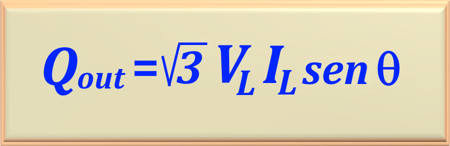
It is also possible to express the reactive power in line magnitudes, according to eq. 105-12.
eq. 105-12
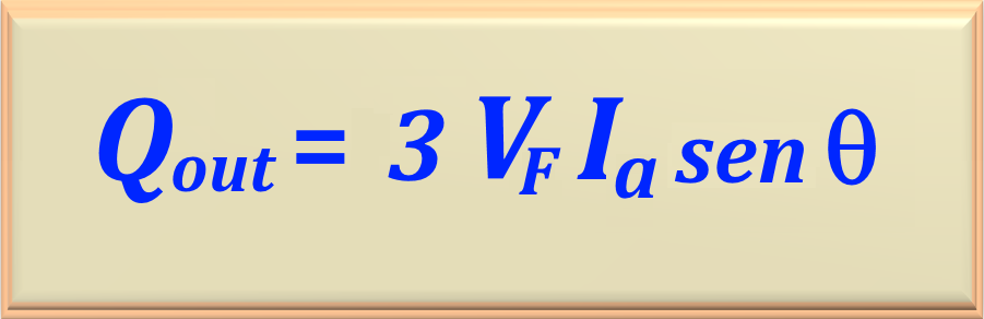
And in phase magnitudes, according to eq. 105-13, where we made Vg = VF
to emphasize the phase greatness.
eq. 105-13
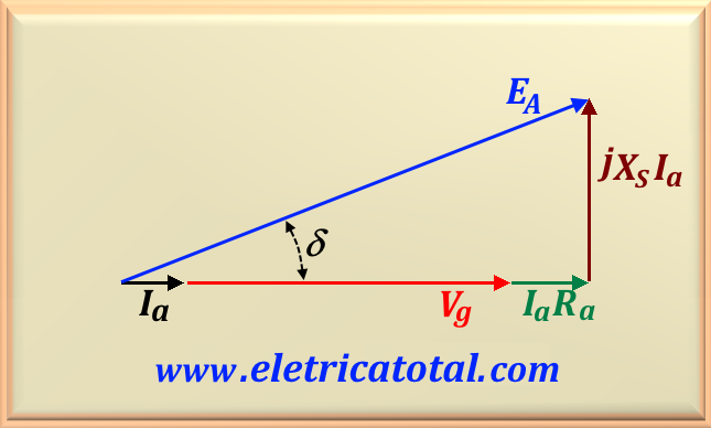
If the armature resistance RA is ignored, considering XS >> RA,
then we can deduce a very useful equation to give an approximate value of the power of
generator output. To deduce this equation, let's examine the phasor diagram in Figure 105-11. This figure
shows a simplified phasor diagram of a generator with the
stator resistance RA ignored.
Figure 105-11
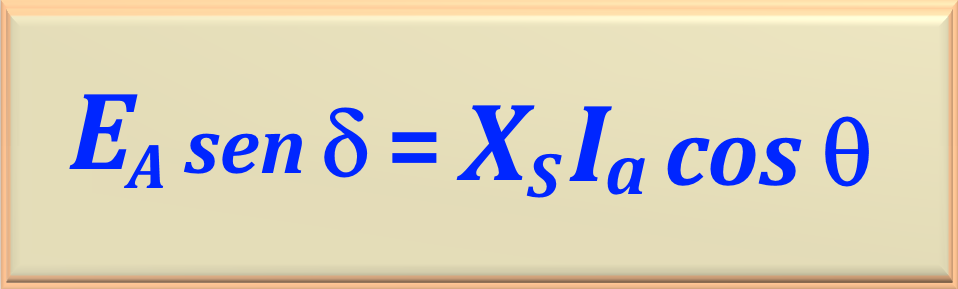
Note that the vertical segment b-c can be expressed by eq. 105-14.
eq. 105-14
We can substitute in eq. 105-11 the value of Ia cos θ
by the algebraic transformation of the above relation. Thus, we will get:
eq. 105-15
This equation stipulates an approximation because we have assumed that the generator resistances are equal
to zero, that is, there are no electrical losses in the machine. So, we can state that
Pout = Pconv.
It is often interesting to know the power a machine has at its shaft. Knowing the converted or output
power and the rotational losses (Prot), it is possible to obtain the power at the machine shaft
using eq. 105-15a, shown below. Rotational losses include friction losses, ventilation, and losses in the machine's iron.
eq. 105-15a
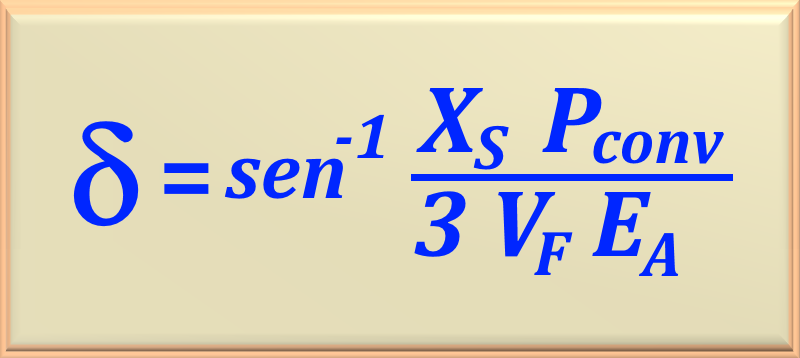
It is also possible to calculate the δ angle by algebraically working eq. 105-15 and obtaining the eq. 105-16 below.
eq. 105-16
We should point out that the eq. 105-14 shows that the power produced by a synchronous generator
depends directly on the δ angle. The angle δ is known as
internal angle or torque angle of the machine. For the
eq. 105-14 it is evident that the maximum power that the generator can supply is when
δ = 90°, because sin δ = 1.
The maximum power indicated by this equation is called the static stability limit
from the generator. Normally, the real generators never arrive nor
close to that limit. Real machines have typical torque angles
at full load from 20 to 30 degrees.
Examining the equations eq. 105-11, eq. 105-13 and eq. 105-15 carefully and,
assuming that VF is constant, the effective output power will be
directly proportional to Ia cos θ and EA sin δ
and the reactive power output will be directly proportional to Ia sin θ.
These observations are useful when plotting phasor diagrams of synchronous generators
with variable payload.
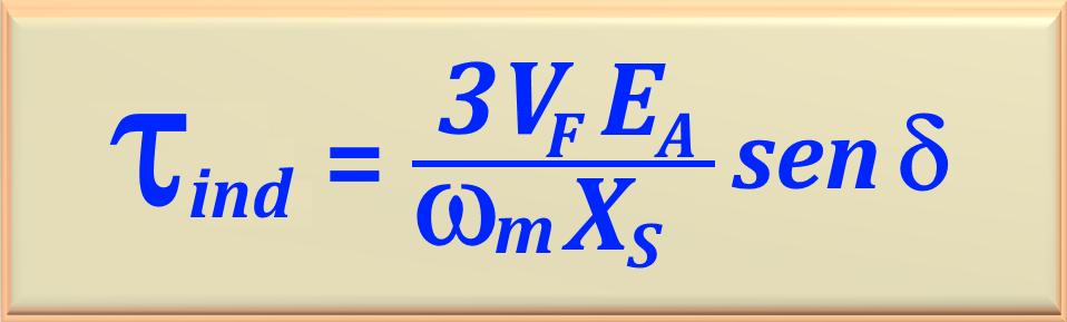
Taking into account eq.105-08 and eq. 105-15 we can easily write
the equation that defines the induced torque on the generator rotor through eq. 105-17.
In the same way as we studied in the chapter referring to transformers, in synchronous machines we also use short-circuit and no-load tests to determine the parameters of synchronous machines.
The equivalent circuit that was deduced earlier for a synchronous generator contained three quantities
that must be determined to fully describe the behavior of
a real synchronous generator. Are they:
The relationship between field current and flux (that is, the field current IF and the
induced voltage EA ).
This is the first step to be performed to determine the parameters of the synchronous generator. Therefore, we must ensure that we do not there is any kind of load connected to the generator terminals. That is, we have the generator in the condition of "empty".
Next, we run the generator at its nominal speed. Since we have no load, then we know that
Ia = 0 and in this case we have EA = VF . Knowing this information, it is possible to construct a plot of EAversusIF. The curve constructed on the graph is called the
empty characteristic. In some literature also known as
open circuit characteristic.
Using the characteristic curve we can find the generated internal voltage EA for any current of
field IF given.
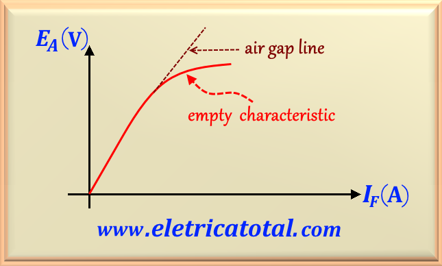
Figure 105-12
In Figure 105-12 we see the empty characteristic typical of a synchronous generator. Note that, at the beginning, the
curve is almost perfectly straight until some saturation is observed with high field currents. The unsaturated iron
of the synchronous machine has a reluctance that is several thousand times less than
the reluctance of the air gap. Thus, in the beginning, almost all the magnetomotive force
is in the air gap and the resulting flux increment is linear. When the iron finally saturates, the iron's reluctance increases
dramatically and the flow increases a lot
more slowly with increasing magnetomotive force. The linear portion of a
empty characteristic is called the air gap line of the characteristic.
After carrying out the empty test and determining the graph EAversusIF, we are able to carry out the short circuit test and determine the various parameters of the generator
synchronous. Like first step, we must short-circuit the output of the generator with a set of ammeters and adjust the field current
IF for the value zero. Thus, the armature current Ia (or the line current
IL) is measured while the field current is gradually increased. Making a table of measurements and placing
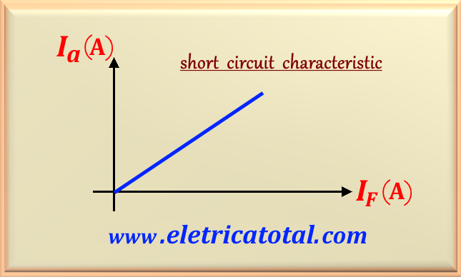
these values on a graph, we will get the so-called short circuit characteristic and we can see this graph in the
Figure 105-13.
Figura 105-13
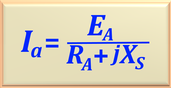
Notice that it's basically a straight line. To understand this, we can look at Figure 105-06 and considering that the
generator terminals are short-circuited (that is, Vg = VF = 0 ), so we can write the value of
Ia by eq. 105-18. In fact, the resulting magnetic induction field in the machine is very small, causing
machine is not saturated, so short circuit characteristic is linear.
eq. 105-18
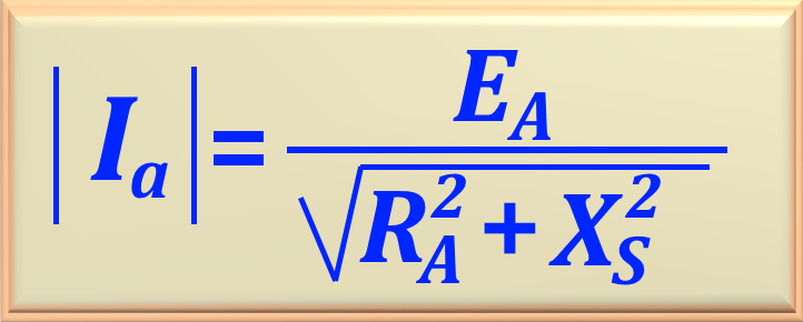
Of course we can write the value of the module of Ia by eq. 105-19.
eq. 105-19
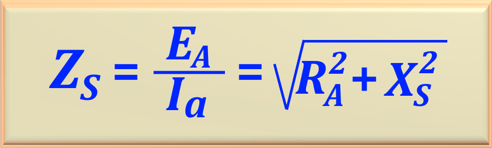
On the other hand, when the machine is short-circuited, we have VF = 0, and this allows us to write
the machine's internal impedance, represented by ZS and given by eq. 105-20.
eq. 105-20
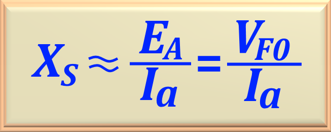
However, in general, we know that we can consider ZS >> RA and so, considering
RA ≈ 0, we can rewrite the eq. 105-20 like:
eq. 105-21
In this equation we are representing the voltage at the output of the no load generator as VF0. So, to
determine the approximate value of the machine's synchronous reactance, XS, with a given field current, we can follow the guide below:
For a given field current IF and using the graph curves empty characterisitic determine the internal
voltage generated EA.
Find the short-circuit armature current using the short circuit characteristic graph for field current
specified.
Using the eq. 105-21 calculate the value of XS.
If you are interested in determining the armature resistance, RA, you can use the following process:
With the machine at rest (inactive), a known DC voltage is applied to the machine terminals and the value of the current flowing is measured
by winding. The quotient between these two magnitudes will be the value of RA. This value is approximate, as it was not considering the skin effect at high frequencies. The approximation can be improved by multiplying the value found by
1.6.
Another parameter used to describe a synchronous generator is the so-called short circuit ratio. It can be set
like:
"It is the ratio between the field current required for the nominal voltage at no load and the
field current required for the rated current of armature in short circuit condition."
The short-circuit ratio allows characterizing the quality of the synchronous machine. For the
same power and rated currents, a machine with lower short-circuit ratio has less volume and weight and,
consequently, lower cost.
When the generator is operating normally and a short-circuit occurs in one or more phases, a short-circuit current
will flow through the armature circuit. This current will depend on the induced EMF and the generator impedance.
The value of the short-circuit current will be the ratio of these two quantities.
This current can damage the generator's armature winding if the
synchronous impedance, ZS, is too small. Therefore, to limit the short-circuit current to a
safe value, modern generators are designed with a high synchronous impedance. The armature resistance,
RA, cannot be increased, as this would increase machine losses.
Thus, modern synchronous generators have high synchronous reactance but low resistance.
The reactance value can be 20 times or more the resistance value. Therefore, for practical purposes, the voltage
drop across the resistance can be ignored when compared to the voltage drop across the reactance.
The voltage regulation of a synchronous generator is defined as the ratio of the no-load and on-load
terminal voltages to the on-load terminal voltage. Since EA is the no-load terminal voltage and
VT = Vg is the on-load terminal voltage, the generator regulation can be given by eq. 105-22,
below.