Problem 64-2
Source: Problem elaborated by the author of the site.
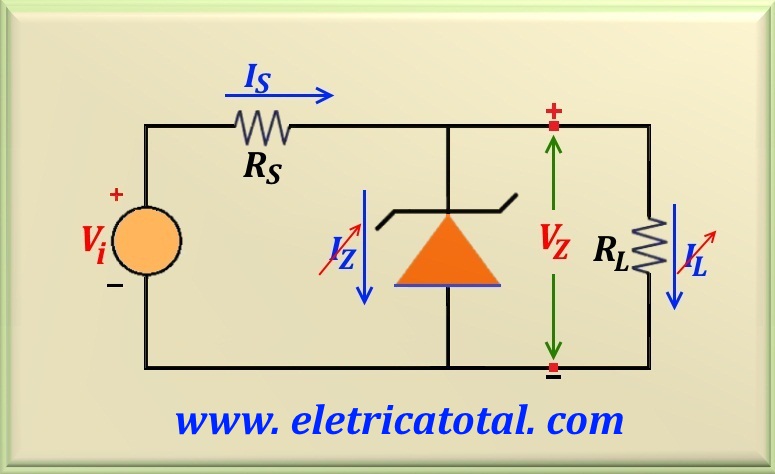
Be the circuit shown in the Figure 64-02.1. Assume that Vi = 20 volts, VZ = 10 volts
and the current in the load ranges from 30 to 90 mA. Verify that zener 1N758 that can dissipate up
to 0.5 W of power can be used in the design.
Figure 64-02.1
Solution of the Problem 64-2
Note that the input voltage is constant but the load is variable. Then there will be variation in the current
flowing through the load and also through the zener. Therefore, we apply the case 2 studied in
the Zener Diode Circuit Design item
(Here!!).
Since zener 1N758 must be used and the zener power is 0.5 watt, we can calculate
IZmax and IZmin, or:
IZmax = PZ / VZ = 0.5 / 10 = 0.05 A = 50 mA
Calculating IZmin, or:
IZmin = 10% IZmax = 10% x 50 mA = 5 mA
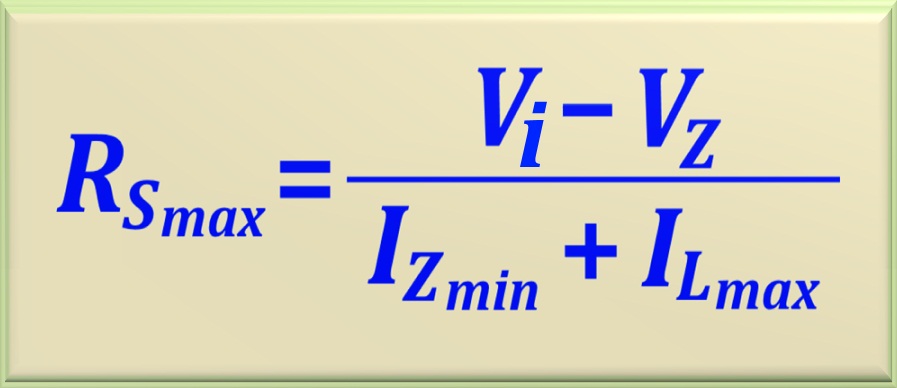
With these two values in mind, we can calculate RSmax and RSmin using the two equations studied. See below:
RSmax = (20 - 10) / (0.005 + 0.09) = 105.3 Ω
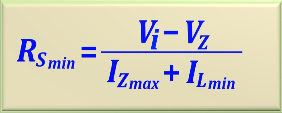
And in turn:
RSmin = (20 - 10) / ( 0.05 + 0.03) = 125 Ω
As is well known, RSmin > RSmax making the project unfeasible. Therefore, we conclude that we can not use zener 1N758 in this project.
To work around this problem, use a zener that allows 1 watt to dissipate, such as the
1N4740 model.
So by recalculating the values to see if you can run the project.
IZmax = PZ / VZ = 1 / 10 = 0.1 A = 100 mA
Calculating IZmin, or:
IZmin = 10% IZmax = 10% x 100 mA = 10 mA
Therefore, the new values of RSmax and RSmin, will be:
RSmax = (20 - 10) / (0.01 + 0.09) = 100 Ω
And in turn:
RSmin = (20 - 10) / ( 0.1 + 0.03) = 76.9 Ω
Now RSmax > RSmin. The commercial value of resistor between these values is 82 ohms and 100 ohms. The value of 100 ohms is discarded because the component would be working at the acceptable limit. Therefore, the best choice for series resistor lies in the value of RSmax = 82 ohms. So:
RS = 82 Ω
We must determine the power that the resistor RS will dissipate in the circuit. The current passing through RS is given by:
IS = (Vi - VZ) /RS = 10 / 82 = 121.95 mA
Note that the current through RS is constant. It does not depend on variations in load because these variations are absorbed by the zener. Then the power dissipated is:
PS = (Vi - VZ) IS = 10 x 0.12195 = 1.2195 W
Therefore, a resistor of 2 W, or rather one of 5 watts may be used. Thus, a greater gap is achieved.
To conclude, calculate the power dissipated by zener. Note that to calculate the power dissipated by the zener, we must use the largest current that flows through it. Thus, the worst situation is when the load consumes the least current.
So, IZmax = IS - ILmin = 0.09195 A = 91.95 mA. Then:
PZmax = VZ (IS - IL) = 10 x 0.09195 = 0.9195 W
Since the power is less than 1 watt then this zener can be used. In addition,
a better solution is to use a zener diode that supports 5 watts.