Problem 64-1
Source: Problem elaborated by the author of the site.
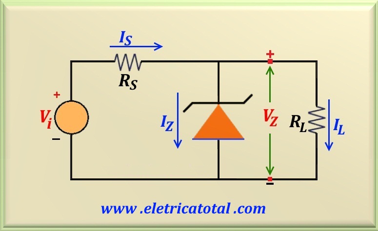
Be the circuit shown in the Figure 64-01.1. Assuming that Vi = 22 volts, VZ = 15 volts and a current at the load equal to 100 mA, check that the 1N4744 zener can dissipate up to
1 watt power, can be used in this project.
Figure 64-01.1
Solution of the Problem 64-1
Since the input voltage and the load are constant, we can apply the case 1, studied in the
Zener Diode Circuit Design item (Here!!). It is known that the zener power 1N4744 is 1 watt, so we can calculate IZmax and IZmin:
IZmax = PZ / VZ = 1 / 15 = 0.067 A = 67 mA
Calculating IZmin, or:
IZmin = 10% IZmax = 10% x 67 mA = 6.7 mA
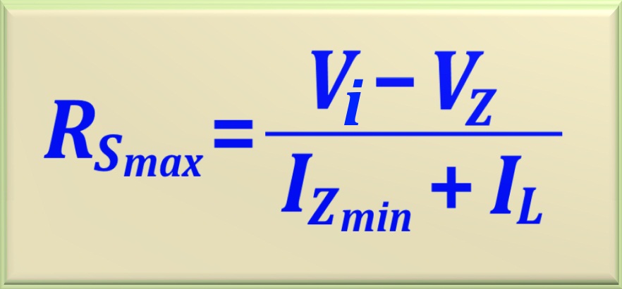
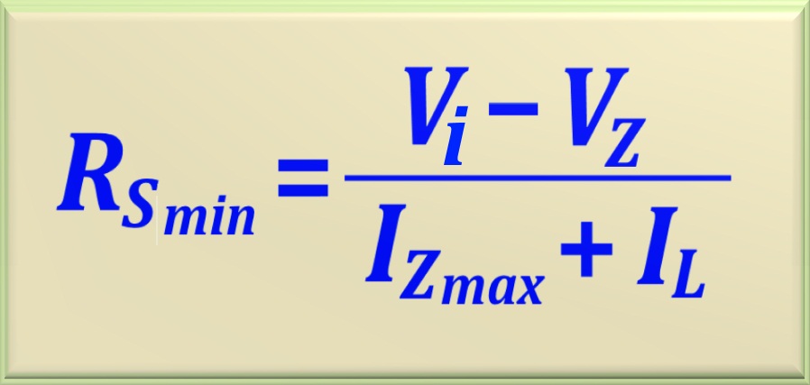
With these two values in mind, we can calculate RSmax and RSmin using the two equations studied. See below:
RSmax = (22 - 15) / (0.0067 + 0.1) = 65.6 Ω
And in turn:
RSmin = (22 - 15) / ( 0.067 + 0.1) = 41.9 Ω
In this way, we can calculate the arithmetic mean of RSmin and RSmax to find a convenient value for the project. Soon:
RS = (RSmin + RSmax) / 2 = 107.5 /2 = 53.75 Ω
Therefore, the nearest commercial resistance value is:
RS = 47 Ω
Of course, you can choose a value like 56 ohms or 62 ohms, because they would be within acceptable values for RS, since RSmin < RS < RSmax .
We must determine the power that the resistor RS will dissipate. The current that pass through RS is given by:
IS = (Vi - VZ) /RS = 7 / 47 = 148.94 mA
Then the power dissipated is:
PS = (Vi - VZ) IS = 7 x 0.14894 = 1.0425 W
Therefore, a resistor of 2 W, or rather one of 5 watts may be used. Thus, a larger gap is achieved.
To conclude, we must calculate the power dissipated by zener. Note that in the equation below,
IZmax = IS - IL. So:
PZmax = VZ (IS - IL) = 15 x 0.04894 = 0.7341 W
Since the power is less than 1 watt then you can use this zener. However, if there is a power interruption in the load, the zener will not be able to absorb the excess current and
will be destroyed. As a solution use a zener diode that supports 5 watts.