In the previous chapters we have studied a very useful application of the diode when it is used with
direct polarization.
However, there are diodes that work, under special conditions, with inverse polarization. These diodes are called ZENER diodes.
There are numerous applications for the Zener diode. One of the main ones is its use as a
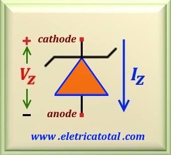
voltage regulator. In the figure below we can see the symbol used to represent the
zener diode. Note the polarity used for it to work as a zener.
If there is inversion in the polarity, it will behave like a common diode. Therefore, always be aware of polarity when working with zener diodes.
Figure 64-01
In the Figure 64-01 we see the schematic representation of a zener, as well as the polarization that we must employ so that it functions as a zener.
Note that polarity is opposite to that used for a common diode. For this polarization we will have on the
zener the voltage Vz for which it was designed.
In the figure we show the direction of electric current Iz on it.
As we said above, the zener diode should work with a reverse polarization. That is, at the cathode a more positive voltage
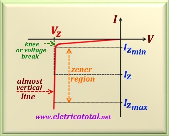
is applied than at the anode. In the Figure 64-02, we represent the characteristic curve of a zener diode.
Notice that by increasing the voltage on the zener, in the negative direction, the electric current is initially null. This is
true to the point where the voltage approaches the ruptura voltage. At this point, there is the so-called "knee",
where the electric current in the zener grows steeply keeping a stable voltage on the zener itself that there is
large variations of current in the zener (evidently within certain limits).
Figure 64-02
Note, on the graph, that as soon as the voltage on the diode reaches the voltage Vz,
the straight line assumes a "almost vertical" characteristic, allowing the voltage to remain stable
over the diode even if the electric current changes. Notice that there are two important points in the graphic.
The first is Iz min, which is the minimum current that the zener needs in order to
maintain the voltage in Vz.
Below this point there will be no guarantee of stable tension on the zener. The second is
Iz max, which is the maximum current that the zener diode supports without failing. The value of this current depends on the voltage of the zener and the power that it can dissipate.
Due to the sharp slope of the line appearing in Figure 64-02, in the zener region, we can say that the zener has a small
resistance or, also called impedance, and that is a characteristic of each zener. Normally, this value
is specified by the manufacturer.
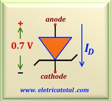
Figure 64-03
We can not ignore what happens when we call a zener diode using direct polarization. In this case, the
zener diode behaves like a common diode, that is, it conducts anode current to the cathode and there will be a voltage
drop on it of 0.7 volts. In the Figure 64-03 we show this situation.
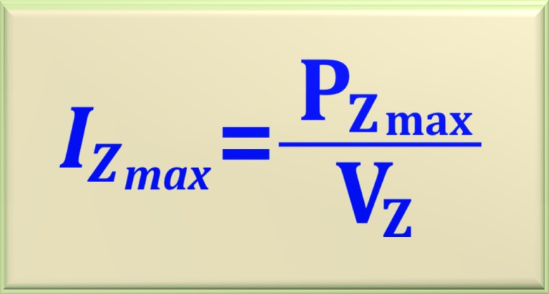
The zener diode is characterized by two basic requirements: the zener voltage and the power that it needs to
support in order to perform its function satisfactorily. Because of the
maximum power and the zener voltage that it can support, we easily calculate the
maximum current with which it can work. Using the equation that defines power, we have:
eq. 64-01
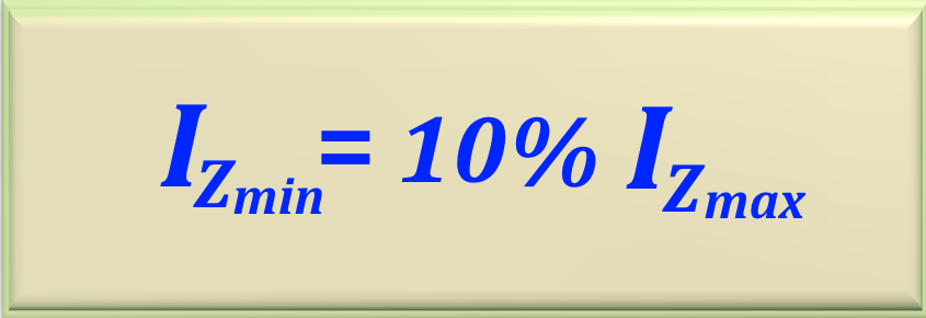
In case of Iz min (minimum current in the zener) it is usual to take its value as
10% of the maximum zener current, Iz max, according to eq. 64-02.
eq. 64-02
There are several commercial of zener models for various different values of voltage and power.
To differentiate them, there are codes that determine the voltage and power of the device. For example,
in the Table 64-01 we present some of the most common in the market. In the left column we have the voltage
that the zener can regulate and the next two columns are the zener codes. The middle column is for zener which can
dissipate at most 0.5 W of power and in the right column those that support up to 1 W.
For all of the features reported above, it is more than enough reason for the zener diode to be employed as voltage regulator.
When we studied the rectifier circuits, we pointed out that one of the problems was the
ripple on the output voltage.
To reduce it, a capacitor was added in parallel with the load.
We saw that the capacitor softened the problem, but it did not eliminate it. So we have the
zener diode as the savior of this situation.
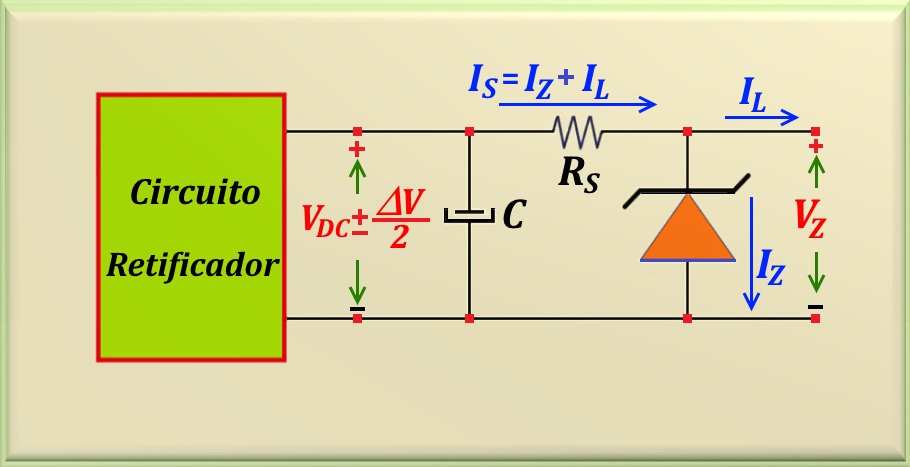
When we use a zener diode as a voltage regulator, we usually use the voltage output of the rectifier, and use a resistor
between the capacitor and zener as a limiter of current.
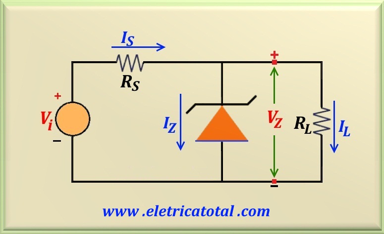
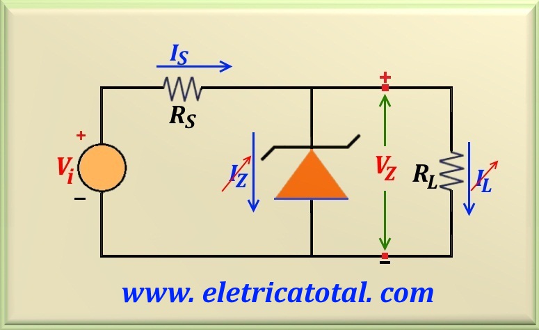
In the Figure 64-04 we can appreciate a typical voltage regulator circuit using a zener diode.
Figure 64-04
Important:
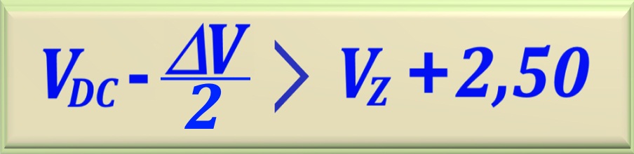
For this circuit to work properly, is very important that the relation below to be satisfied.
eq. 64-03
Note that in this equation, VDC - (ΔV/2) represents the minor voltage at the output of
the rectifier circuit. As there will be a voltage drop in the resistor Rs, we have to leave a minimum
clearance of 2.50 volts (this may be more), otherwise the zener diode will not be able to guarantee stable output voltage.
Some authors, and even teachers, accept values of the order of 0.5 to 1 volt. In theory, it may be. But if it is a
design to be put into practice, never leave less than 2.5 volts or there will be great possibilities your design will not work.
Attention
Another important situation in projects with zener diodes is the possibility of the load suffering
some kind of problem, such as a rupture thereof and become an open circuit. In this case, the current
that had previously circulated through the load must now be absorbed by the zener diode. If zener does not
support this increase in current, it will be damaged as it will dissipate a power above its capacity.
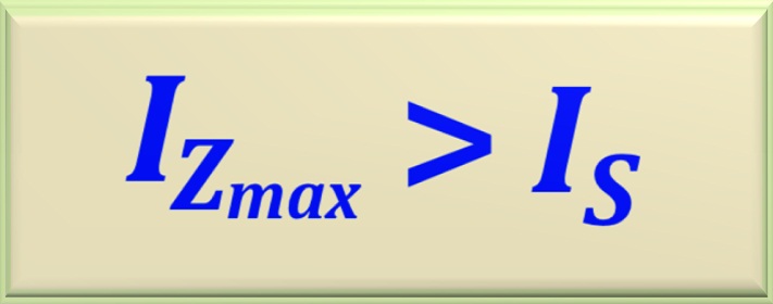
To avoid this possibility, we must verify if the equation below is satisfied by the circuit, not forgetting
that IS = IZ + IL.
eq. 64-04
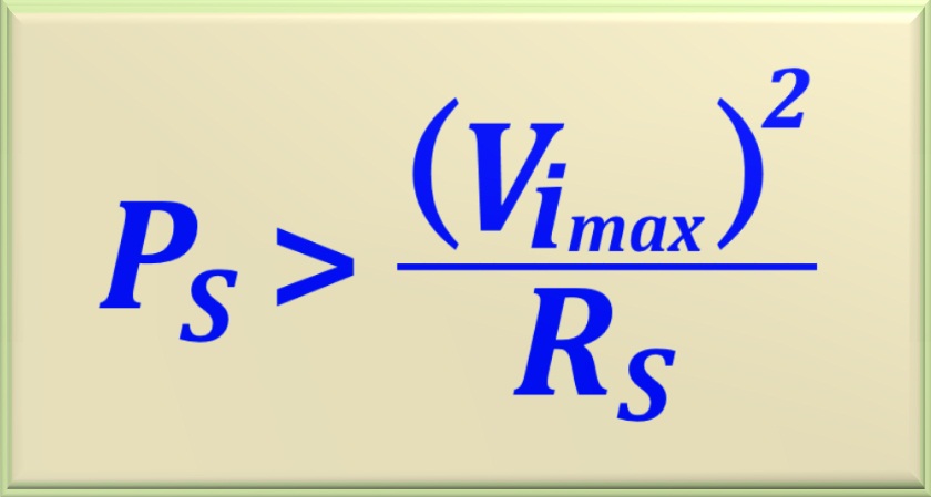
Another possibility is that the load is not an open circuit, but a short circuit. In this case the zener diode will
not be damaged. However, the resistor Rs shall withstand the excess current flowing through it. Then, in the
design, the equation below must be satisfied.
eq. 64-05
When the input voltage is constant, then Vimax = Vi.
And when the input voltage is not constant then Vimax = Vi + (Δ V/2)
For the circuit design of a voltage regulator using a zener diode we need some data, such as the output voltage,
the maximum electric current that will circulate through the load, and also the output voltage of the rectifier plus the
ripple, ΔV. In the problems and evidence of this area, we find some variations of data provided, but there should
be a minimum of data that is sufficient to elaborate the project.
Another relevant fact is that the value of Rs can assume minimum and
maximum values, and will depend on the minimum and maximum voltage at the rectifier output. So we can
establish two basic principles for the project.
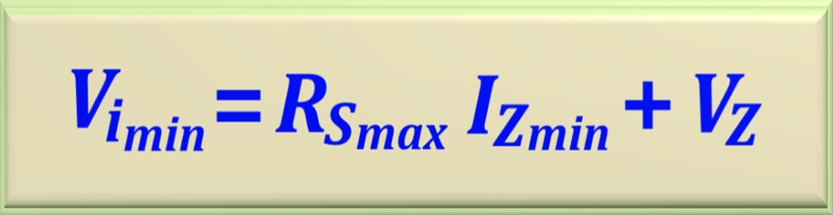
1st Principle -
In order for the zener diode to maintain the stable voltage at the output, it must
operate with a current greater than the calculated minimum current,
IZmin. In other words: IZ > IZmin. As a consequence, this limits the minimum
value of the input voltage in the circuit, given by Vi(min) = VDC - (ΔV/2), as well as
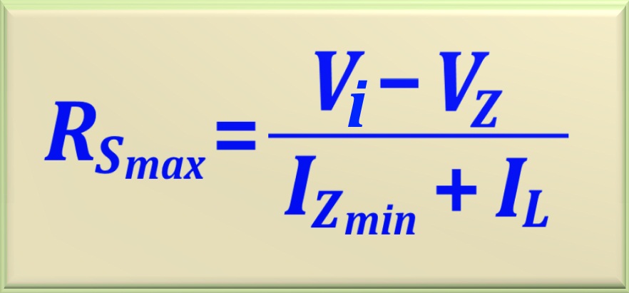
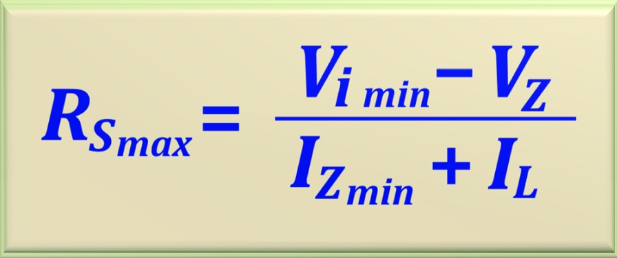
the maximum value of the series resistance of the circuit, represented by RSmax. These limitations
allow us to write the equation below.
eq. 64-06
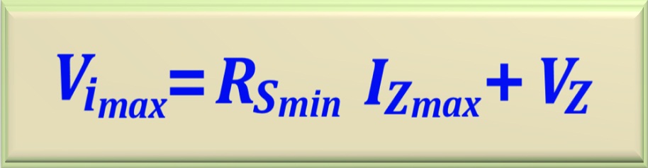
2nd Principle -
If the current passing through the zener diode is
greater than the maximum calculated current, IZmax, certainly the zener diode will be damaged.
As a consequence, this limits the maximum value of the input voltage in the circuit, given by
Vi(max) = VDC + (ΔV/2), as well as the minimum value of the series
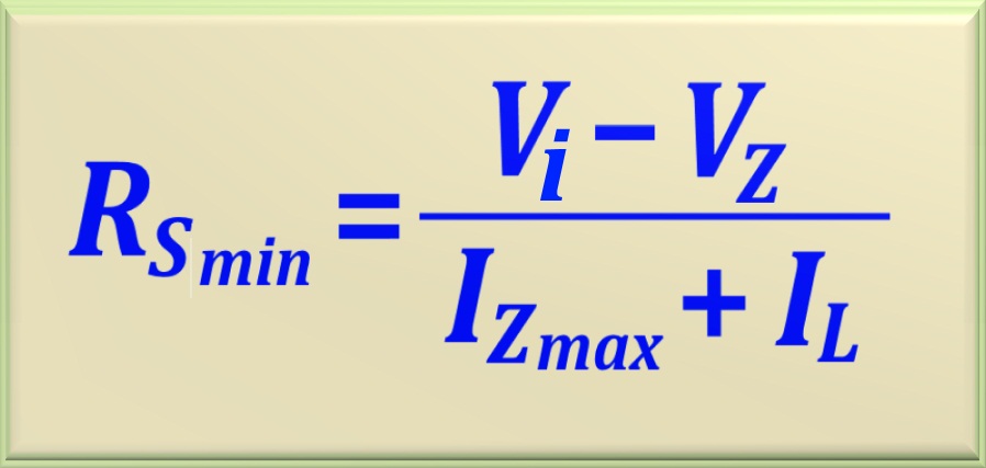
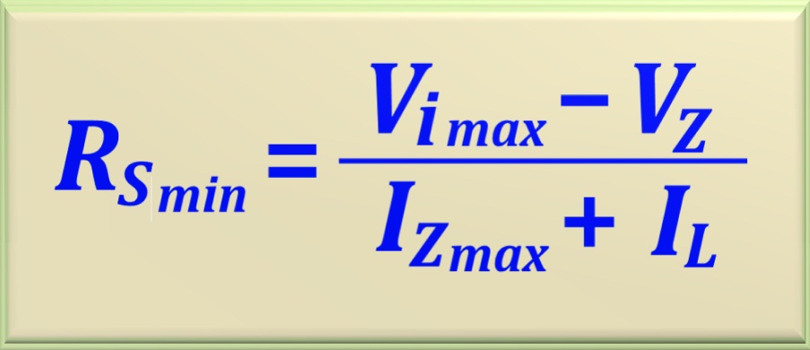
resistor of the circuit, represented by RSmin. From this, we conclude that we should have
IZ < IZmax. These limitations allow us to write the equation below.
eq. 64-07
Based on these two principles we can analyze four cases that may occur.
Constant Load (RL = cte) and Constant Input Voltage
In this case, the constant load means that the current in the load depends only on the voltage
VZ. On the other hand, since the input voltage is also constant (it may be a battery), then zener
is being used as a reductor of the input voltage. This circuit can be used when we need a voltage less than that
supplied by the rectifier. In the Figure 64-05 we can appreciate a typical circuit used for this purpose, where
Vi represents the source with constant voltage.
Figure 64-05
Based on the circuit, we easily conclude that:
IS = IZ + IL
Since we assume that the electric current in the load is constant, then if we work with the
minimum current for the zener diode, we will be establishing the maximum value that the resistance
RS can assume. On the other hand, if we work with the maximum current
for the zener diode, we will be establishing the minimum value that the resistor RS can assume.
So, depending on the choice, we can work with the two equations below.
eq. 64-08
eq. 64-09
Realize that to find RSmax we use IZmin and for
to calculate RSmin we use IZmax. In general, in the tests, these variables
are the most requested in the problem solving. And to find the practical value of RS, we can do
the arithmetic mean of the calculated values. If you are prompted by the problem, we can adjust the value of
the RS found for the nearest commercial value.
Example 1
As an example, we will use the above circuit, assuming that Vi = 14 volts, VZ = 10 volts
and a load current equal to 100 mA. Let's use the 1N4740 zener that can dissipate up to 1 watt of power.
Solution
Since we know the voltage and power of the zener, we can calculate IZmax and IZmin, or:
IZ max = PZ / VZ = 1 / 10 = 0.1 A = 100 mA
Now we can calculate IZ min, or:
IZ min = 10% x IZ max = 10% x 100 mA = 10 mA
With these two values we will calculate RS min and RSmax using the
equations that we developed at the beginning of this case. Like this:
RS min = (14 - 10) / (0.1 + 0.1) = 20 Ω
And in turn:
RS max = (14 - 10) / (0.01 + 0.1) = 36.67 Ω
In this way, we can calculate the arithmetic mean of RSmin and RSmax to find a convenient
value for our project. Soon:
RS = (RS min + RS max) / 2 = 56.67 /2 = 28.33 Ω
Therefore, a commercial resistance value closer to the value found is:
RS = 27 Ω
Of course, we could have chosen a value as 22 ohms or 33 ohms, because they would be within acceptable values for
RS, since RSmin < RS < RSmax .
We must determine the power that the resistor RS will dissipate in the circuit. The current passing through
RS is given by:
IS = (Vi - VZ) /RS = 4 / 27 = 148.15 mA
Then the power dissipated is:
PS = (Vi - VZ) IS = 4 x 0.14815 = 0.5926 W
Therefore, we can use a resistance of 1 W, or rather one of 2 watts. So we got a bigger slack.
To conclude, we can calculate the power dissipated by the zener.
PZ = VZ. (IS - IL) = 10 x 0.04815 = 0.4815 W
Some considerations
With the chosen value of RS we get a security factor greater than
(1 / 0.4815)> 2 for the zener diode.
If RS = 33 Ω then PZ = 0.21 W. The zener works with low power dissipation.
And if RS = 22 Ω
then PZ = 0.82 W. In this case, the zener will work very close to its power limit.
Note how the chosen value of RS influences the power dissipated by the zener.
Another situation: let us suppose that the load suffers a
malfunction, such as an interruption in the circulation of electric current through it. In this case, the zener will
have to absorb the excess current. In this example, if this happens, the zener will be damaged, because the current
that will circulate through it is above the maximum value that it supports. This happens for any value of
RS calculated. Check out !!!
These are just a few considerations that should be taken into account in the project.
Now let's look at the case where we hold the voltage V of the source and change the load, that is,
IL can range from a minimum value to a maximum value, which will certainly be explained in the problem statement.
This case is a particularity of the previous.
The zener continues to be used as a reductor of voltage, but the current in the load may vary. An example would be to feed a
small amplifier that amplifies the signal coming from a microphone. When no one speaks to the microphone, the current consumption of
the amplifier is minimal. However, when someone speaks to the microphone, the current consumption increases considerably.
Let's think with logic: if zener is able to maintain a stable (constant) voltage and voltage
Vi is also constant, obviously the electric current through the resistor
RS will also be. This implies that if the current in the load changes, then the current in the zener
should also vary. And in the same amount as the change in load. With this in mind, for the circuit to work properly, we must
fulfill two requirements:
a) When load is consuming the maximum current , we have to ensure that the current in zener
is at least equal to the minimum current of the zener , that is, we have to satisfy IZ ≥ IZmin,
so that the zener can maintain a stable voltage at the output.
b) When the load is consuming the minimum current, then the electric current in zener,
under no hypothesis, may be greater than the maximum current of zener, that is, IZ ≤ IZmax.
Otherwise, the zener will be damaged as it will dissipate a power above its specifications.
Based on this information we can write the equations that allow to find the maximum and minimum values of
RS.
eq. 64-10
eq. 64-11
Realize that to find RS max we use IZmin together with
ILmax and to calculate RSmin we use IZmax together with ILmin.
As in case 1, to find the practical value of RS, we can do the arithmetic mean of the calculated values.
If you are prompted by the problem, we can adjust the
RS found for the nearest commercial value.
In the Figure 64-06 we can see the circuit that represents this situation. It should be noted that, when the value
of resistor RS is chosen, for the circuit to work satisfactorily, it is worth at any moment the relation:
IS = IZ + IL
Figure 64-06
Example 2
As an example, we will use the circuit show in the Figure 64-06, assuming that the voltage input Vi = 20 volts,
VZ = 12 volts and a load current ranging from 20 to 80 mA. Let's use the zener 1N4742 which
can dissipate up to 1 watt power.
Solution
Since we know the voltage and power of the zener, we can calculate IZmax and IZmin, or:
IZ max = PZ / VZ = 1 / 12 = 83.33 mA
Now we can calculate IZmin, or:
IZ min = 10% IZ max = 10%. 83.33 mA = 8.33 mA
With these two values we will calculate RSmin and RSmax using the two equations
we developed at the beginning of this case. Like this:
RS min = (20 - 12) / (0.0833 + 0.02) = 77.44 Ω
And in turn:
RSmax = (20 - 12) / (0.00833 + 0.08) = 90.56 Ω
As in the previous case, we will calculate the arithmetic mean of the values found:
RSmax = (77.44 + 90.56) / 2 = 84 Ω
The nearest commercial value is:
RS = 82 Ω
Let's calculate the current that flows through RS.
IS = (Vi - VZ) /RS = 8 / 82 = 97.56 mA
Then the power dissipated in RS is:
PS = (Vi - VZ) .IS = 8 x 0.09756 = 0.78 W
So we can use a resistor of 1 W or 2 W.
Now let's calculate the current in the zener diode as a function of the current variation in the load. Note that when the
load consumes 80 mA, in the zener we will have a current of:
IZ = IS - IL = 97.56 - 80 = 17.56 mA
And when the load consumes 20 mA, the current in the zener diode will be:
IZ = IS - IL = 97.56 - 20 = 77.56 mA
That is, the zener diode is working to its specifications. So we can write that the current of the zener vary between the values
17.56 ≤ IZ ≤ 77.56 mA.
Constant load (RL = cte) and Variable Input Voltage
In this case, where we keep the load fixed, that is, IL is constant, there will be variations
in the zener current, IZ. This is because the input voltage is no longer fixed, so we will have a ripple .
Like this, when there is variation in tension, there will be variation in the current that circulates through
RS. This variation will be reflected in the zener current.
Therefore, for the circuit to work properly we must fulfill two requirements:
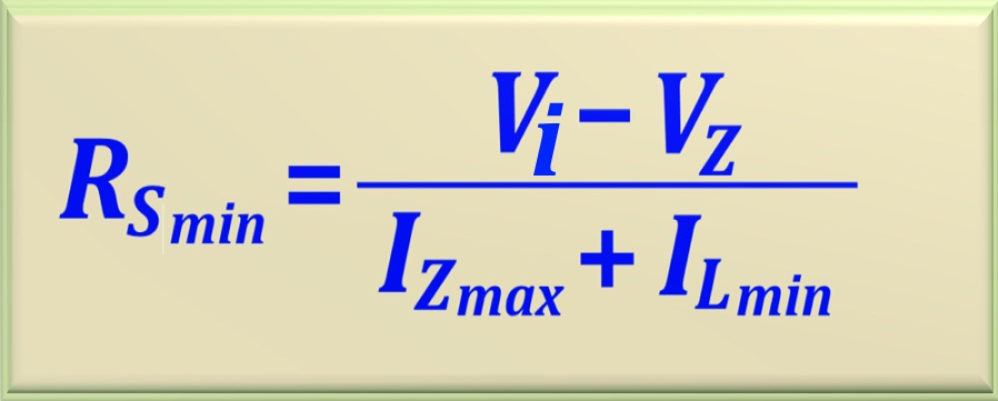
a) When the input voltage is maximum, the current in the zener will also be maximum
and this will determine the minimum value of RS.
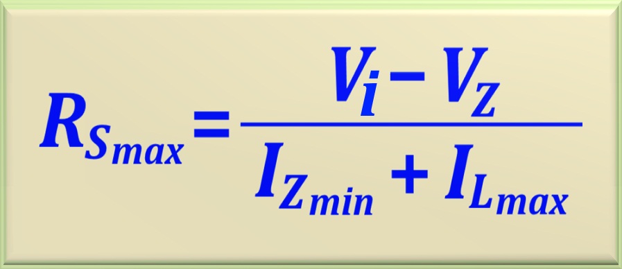
b) And when the input voltage is minimum, the current in the zener will also be minimum
and this will determine the maximum value of RS.
Based on this information we can write the equations that allow to find the maximum and minimum values of
RS.
eq. 64-12
eq. 64-13
Realize that to find RSmin we use IZmax together with Vi(max)
and to calculate RSmax we use IZmin together with Vi(min). As in
other cases, in order to find the practical value of RS, we can do the arithmetic mean of the
calculated values. If you are prompted by the problem, we can adjust the
RS found for the nearest commercial value.
See in the Figure 64-07 a typical circuit for this case.
The latter case is characterized by all the currents and voltages involved being variables, except for the voltage on
the zener, which MUST be constant. Therefore, for the circuit to function properly, we must fulfill two requirements:
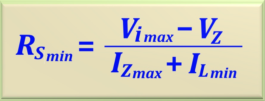
a) When the input voltage is maximum, the current in the zener will also be maximum
and the current in the load will be minimum . This will determine the
minimum value of RS.
b) And when the input voltage is minimum, the current in the zener will also be minimum
and the current in the load will be maximum. This will determine the
maximum value of RS.
Based on this information we can write the equations that allow to find the maximum and minimum values of
RS.
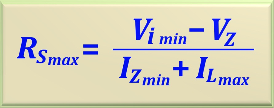
eq. 64-14
eq. 64-15
Realize that to find RSmin we use IZmax together with
Vi(max) and ILmin. To calculate RSmax we
use IZmin together with Vi(min) and ILmax. As in other
cases, in order to find the practical value of RS, we can make the
arithmetic mean of the calculated values. If you are prompted by the problem, we can adjust the
RS found for the nearest commercial value.
See in the Figure 64-08 a typical circuit for this case.