In three-phase transformers, there is a phase difference between the phasors representing the voltage in the
primary winding and in the secondary winding. This phase difference angle depends on the connection of the windings
on each side of the transformer and the way the winding is constructed. Due to this phase difference, when it is intended
to create a parallel connection between two three-phase transformers using certain connections, it is possible that the
voltages in the secondary are equal in magnitude but out of phase with each other, preventing the parallel connection or
requiring a change in the order in which the different phases of the secondary of one of the transformers are connected.
Since the phase shift between the primary and secondary voltages of a three-phase transformer is defined at the time
of construction (when the coils are constructed and the phase windings are connected), each transformer has information
on its nameplate about that phase shift angle, provided by means of a hourly index
(integrating the connection symbol) or a clock representation..
When constructing the coils of a transformer, there are several possibilities for assembling the coils in the core of the transformer.
One way of assembling the coils is shown in Figure 96-01.
In this case, the MMF generated by the primary winding gives rise to a magnetic flux in the core from the N
terminal to the A terminal. And in the secondary winding, the magnetic flux is from the a terminal to the n terminal.
Figure 96-01
Another possibility for assembling the coils in the core of this transformer is such that the MMF
generated by the primary gives rise to a magnetic flux in the core with the direction from the N
terminal to the A terminal. This way of assembling the coils is shown in Figure 96-02. And in the
secondary winding, the magnetic flux will be from the n terminal to the terminal a.
Figure 96-02
The two different assembly possibilities presented above result in two different characteristics for the voltage
at the coil terminals: either the voltage at the secondary terminals is in phase with the primary voltage, or it is in phase opposition.
In this way, a direction is assigned to the flux generated by the primary winding coil and it is assumed that, in the
transformer column, the magnetic induction flux always maintains the same direction. Thus, it is verified that, in each
secondary coil, it is necessary to associate a direction for the electromotive force induced by the magnetic flux.
With this, the voltage that appears at the terminals of the secondary coil is properly characterized.
The nomenclature of the angles between the windings of a three-phase transformer is determined based on two main factors:
the connection of the windings (whether in a star, triangle or mixed combinations) and the direction of the magnetic flux generated
during the construction of the equipment. During the manufacturing process, the polarity of the windings on the primary side is
defined, thus assigning a direction to the magnetic flux. This same flux, when inducing voltages in the secondary windings,
can result in angular phase shifts expressed by means of an index often represented in terms of hours on an analog clock.
According to established standards and other technical references, the representation of this angle is standardized by dividing
the 360° into 12 equal intervals, where each hour is equivalent to 30°. Thus, when identifying
the phase difference between the primary winding voltage and the induced voltage in the secondary winding, an integer
(from 0 to 11) is used to express the phase shift in 30° increments. This angle is indicated
by the hour hand (smaller hand) of an analog clock.
For those unfamiliar with analog clocks, Figure 96-03 illustrates a basic type and shows that the angle between
consecutive numbers is 30°.
Figure 96-03
For example, if in this notation we have Dy11,
this means that:
The letter D indicates that the primary is connected in a delta pattern.
The letter y, to the right of the letter D, indicates that the secondary is connected in a star pattern.
The number 11 means that there is a phase shift of 11 × 30° = 330° in relation to a chosen reference frame,
and which, under a clock convention, indicates that the secondary is ahead of the primary by 30°.
This nomenclature allows not only to identify the winding configuration, but also to ensure the correct operation of the transformer in systems where parallel equipment or phase compatibility is critical. In this way, the hour index (or clock number) aims to standardize and simplify the identification of phase shift angles, avoiding phase incompatibility problems that could lead to short circuits or damage to equipment.
In short, the nomenclature results from the combination of the physical configuration of the windings (delta, star, etc.) and the quantification of the phase shift angle (measured in multiples of 30° and represented by the hour index), allowing a standardized and intuitive representation of the vector groups of three-phase transformers.
We have already studied the possible connections in three-phase transformers, the main ones being: Delta, Star and Zig-zag.
So, let's study the main types of possible connections, nomenclature and arrangement of the windings in three-phase systems.
To represent the voltages in the primary, we will use indexes with capital letters (for example, VAN)
and for the voltages in the secondary, we will use indexes with lowercase letters (for example, Van).
The Star - Star connection allows 6 (six) different types of interconnection, resulting in 6 (six)
nomenclatures, namely: Yy 0, Yy 2, Yy 4, Yy 6, Yy 8 and Yy 10.
These different nomenclatures are the result of the polarity and the assembly
of the windings in the transformer core.
In the Figure 96-04, Figure 96-05 and Figure 96-06 represent the connections
Yy 0, Yy 4 and Yy 8. Note how there is a cyclic permutation between the secondary phases (a - c - b).
To determine the number that accompanies the literal part of the connection, we must
analyze the phase difference between the primary phase voltage, VAN, and the secondary phase voltage, Van. It will be a multiple of 30°.
This allows us to identify the number that accompanies the connection identification.
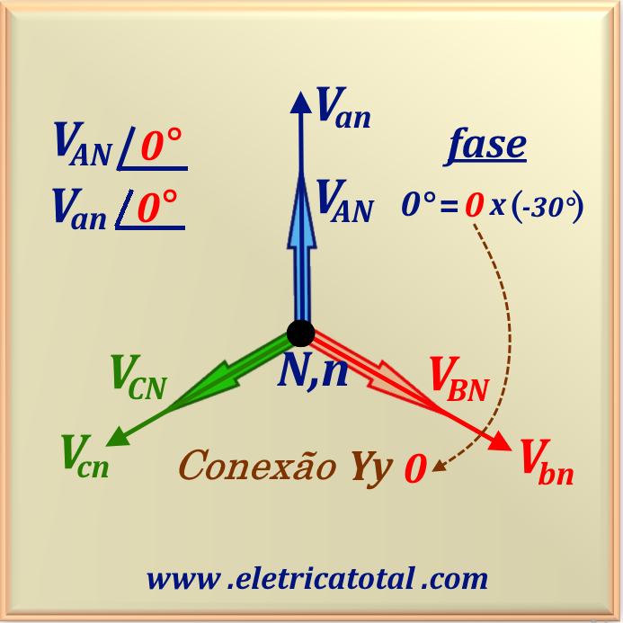
In the case of the Yy 0 connection, it is clear that VAN and Van are in phase, i.e., the phase difference is 0°.
Therefore, 0 accompanies Yy, identifying the type of connection. Zero is represented by the number 12 on an analog clock.
In other words, the phasor Van points vertically upwards.
Figure 96-04Figure 96-05Figure 96-06
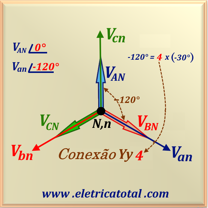
In the case of the Yy 4 connection, it can be seen that Van is 120° behind VAN.
Dividing this angle by 30°, we obtain the number that identifies the connection, that is, 4. The Van phasor points to the
number 4 on an analog clock.
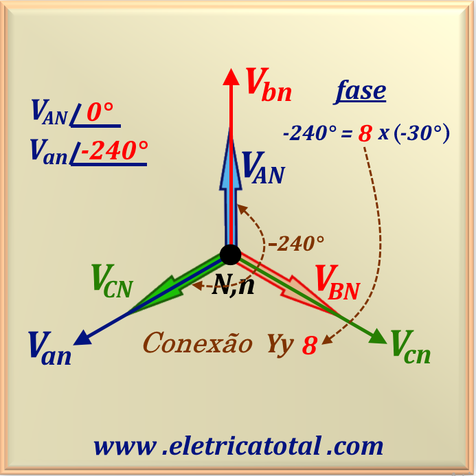
And in the case of the Yy 8 connection, it can be seen that Van is 240° behind VAN.
Dividing this angle by 30°, we obtain the number that identifies the connection, that is, 8. The phasor Van points to the
number 8 on an analog clock.
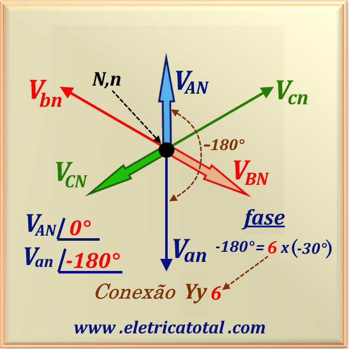
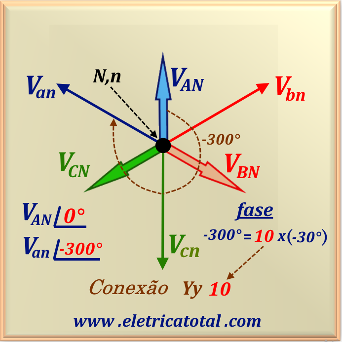
Now, let's analyze the group of connections identified as Yy 2, Yy 6 and Yy 10. These connections are represented in
Figure 96-07, Figure 96-08 and Figure 96-09. Note that, in relation to the primary phase voltage,
VAN, in all three cases there is a secondary phase voltage out of phase by 180°,
occurring in a cyclic manner (b - a - c).
Figure 96-07Figure 96-08Figure 96-09
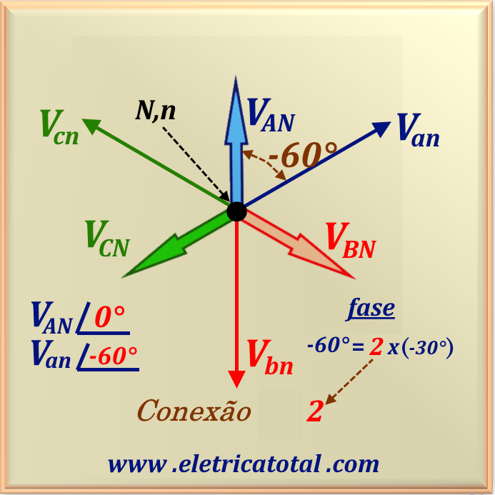
In the case of the Yy 2 connection, it can be seen that Van is 60° behind VAN.
Dividing this angle by 30°, we obtain the number that identifies the connection, that is, 2. The phasor Van points to the
number 2 of an analog clock.
In the case of the Yy 6 connection, it can be seen that Van is 180° behind VAN.
Dividing this angle by 30°, we obtain the number that identifies the connection, that is, 6. The phasor Van points to the
number 6 of an analog clock.
And in the case of the Yy 10 connection, it can be seen that Van is 300° behind VAN.
Dividing this angle by 30°, we obtain the number that identifies the connection, that is, 10. The Van phasor points to the
number 10 of an analog clock. It is also possible to state that the Van phasor is 60° ahead
of the VAN phasor.
For the Yy 0 connection, the secondary winding of phase a must be placed on the same leg of the core as the winding of phase A of the primary. And the polarity must be additive. In this case, there is no phase shift between the phases of the primary and secondary voltages. Therefore, it is said that this type of connection has a real transformation ratio.
All other types of connections have complex transformation ratios, since the phase shift differs from zero.
In the case of the Yy 4 connection, the winding that must be positioned on the same leg of the core corresponding to the primary phase A winding is the secondary phase c, as shown in Figure 96-05.
Therefore, we have that the secondary phase voltage lags behind the primary phase voltage by 120°. The polarity must also be additive.
In the case of the Yy 8 connection, the winding that must be positioned on the same leg of the core corresponding to the primary phase A winding is the secondary phase b, as shown in Figure 96-06. Thus, we have that the secondary phase voltage lags behind the primary phase voltage by 240°. The polarity must also be additive.
The other three configurations require the windings to have subtractive polarity..
In the Yy 2 type connection, the secondary winding of phase b must be placed on the same leg of the core as the winding of phase A of the primary. And the polarity must be subtractive. In this case, the secondary phase voltage,
Van, is 60° behind the primary phase voltage, VAN.
In the Yy 6 type connection, the secondary winding of phase a must be placed on the same leg of the core as the winding of phase A of the primary. And the polarity must be subtractive. In this case, the phase voltage of the secondary,
Van, is 180° behind the phase voltage, VAN, of the primary.
In the Yy 10 type connection, the secondary winding of phase c must be placed on the same leg of the core as the winding of phase A of the primary. And the polarity must be subtractive. In this case, the secondary phase voltage, Van, lags behind the primary phase voltage, VAN by 300°.
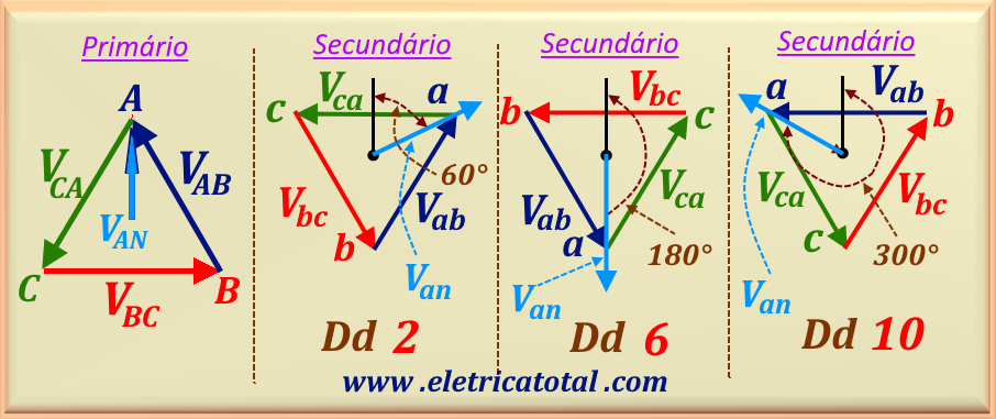
Similar to the star - star connection, the delta - delta connection also has 6 (six) different types of interconnection,
which give rise to 6 (six) nomenclatures: Dd 0, Dd 2, Dd 4, Dd 6, Dd 8 and Dd 10.
In this type of connection, the transformation ratio is always given by the ratio between the primary line voltage and the secondary line voltage.
The most commonly used connection types in manufacturing are Dd 0 and Dd 6.
In Figure 96-10, we present illustrations of the Dd 0, Dd 4, and Dd 8 configurations. Note that they are
similar to the Yy connections. They form a triangle through points A, B, and C where the sides of the triangle
represent the primary line voltages VAB,
VBC, and VCA. And in the secondary, the triangle is formed by the points a, b
and c, where the sides of the triangle represent the secondary line voltages Vab,
Vbc and Vca. By plotting the primary and secondary phase voltages, we can determine the
correct nomenclature of the connections.
Figure 96-10
In the case of the Dd 0 connection, it is clear that VAN and Van are in phase, i.e., the phase difference is zero.
Therefore, 0 accompanies Dd, identifying the type of connection. Zero is represented by the number 12 on an analog clock.
In other words, the phasor Van points vertically upwards.
In the case of the Dd 4 connection, it can be seen that Van is 120° behind VAN.
Dividing this angle by 30°, we obtain the number that identifies the connection, that is, 4. The phasor Van points to the
number 4 of an analog clock.
And in the case of the connection Dd 8, it can be seen that Van is 240° behind VAN.
Dividing this angle by 30°, we obtain the number that identifies the connection, that is, 8. The phasor Van points to the
number 8 of an analog clock.
Now, let us analyze the group of connections identified as Dd 2, Dd 6 and Dd 10. These connections are
represented in Figure 96-11. Note that, in relation to the primary phase voltage,
VAN, in all three cases the secondary phase voltage appears to be out of phase by 180°,
occurring in a cyclic manner (b - a - c).
Figure 96-11
In the case of the Dd 2 connection, it can be seen that Van is 60° behind VAN.
Dividing this angle by 30°, we obtain the number that identifies the connection, that is, 2. The phasor Van points to the
number 2 of an analog clock.
In the case of the Dd 6 connection, it can be seen that Van is 180° behind VAN.
Dividing this angle by 30°, we obtain the number that identifies the connection, that is, 6. The phasor Van points to the
number 6 of an analog clock.
And in the case of the connection Dd 10, it is clear that Van is 300° behind VAN.
Dividing this angle by 30°, we obtain the number that identifies the connection, that is, 10. The phasor Van points to the
number 10 of an analog clock.
For the Dd 0 connection, the secondary line voltage winding, Vab, must be placed on the same leg of the core as the primary line voltage winding, VAB. And the polarity must be additive. In this case, there is no phase shift between the primary and secondary voltage phases.
Therefore, this type of connection is said to have a real transformation ratio.
All other types of connections have complex transformation ratios, since the phase shift differs from zero.
In the case of the Dd 4 connection, the winding that must be positioned on the same leg of the core as the primary line voltage winding,
VAB, is the secondary line voltage winding, Vca, as shown in Figure 96-10.
Thus, the secondary line voltage lags the primary line voltage by 120°. The polarity must also be additive.
In the case of the Dd 8 connection, the winding that must be positioned on the same leg of the core as the primary line voltage winding,
VAB, is the secondary line voltage winding, Vbc, as shown in Figure 96-10. Thus, the secondary line voltage
lags the primary line voltage by 240°. The polarity must also be additive.
The other three configurations require the windings to have subtractive polarity..
In the Dd 2 connection, the secondary line voltage winding, Vbc, must be placed on the same leg of the core as the primary line voltage winding, VAB. And the polarity must be subtractive. In this case, the secondary line voltage,
Van, lags 60° behind the primary line voltage, VAN, as shown in
Figure 96-11.
In the Dd 6 type connection, the secondary line voltage winding, Vab, must be placed on the same leg of the core as the primary line voltage winding, VAB. And the polarity must be subtractive. In this case, the secondary line voltage,
Van, lags 180° behind the primary line voltage, VAN.
In the Dd 10 type connection, the secondary line voltage winding, Vca, must be placed on the same leg of the core as the primary line voltage winding, VAB. And the polarity must be subtractive. In this case, the secondary line voltage, Van, lags 300°
behind the primary line voltage,
VAN.
For a three-phase transformer bank connected in Delta in the primary and in Star in the secondary, the phase shift angle
between the primary and secondary voltages depends on the polarities and the assembly of the windings in the transformer core. This type of
connection presents a complex transformation ratio and has 6 (six) groups of phasor diagrams, represented by:
Dy 1, Dy 3, Dy 5, Dy 7, Dy 9 and Dy 11.
NIn the diagrams shown below, we use the primary phase voltage, VAN, as a reference. For each type of connection analyzed, we compare the phase between VAN and Van to determine the phase shift angle. In this connection, there will always be a phase shift multiple of 30° between these two voltages. It is also possible to note that, in relation to the primary phase voltage,
VAN, in all three cases, a secondary phase voltage appears that is ahead by 90° (or behind by 270°),
in a cyclical manner (c - b - a).
Figure 96-12
The connections Dy 1, Dy 5, and Dy 9 are connected in the subtractive configuration.
The following considerations relate to
the diagrams shown in Figure 96-12.
In the case of the Dy 1 connection, it is visible that Van lags
by 30° relative to the primary phase voltage, VAN.
This means that the phasor Van points to the number 1 on an analog clock. This number is accompanied
by the prefix Dy, which identifies the type of connection.
In the case of the Dy 5 connection, the phase voltage Van lags
by 150° with respect to the voltage VAN. Note that in this case the phasor Van points to the number 5
on an analog clock.
And in the case of the Dy 9 connection, the phase voltage Van lags
by 270° with respect to the voltage VAN and the phasor Van points to the number 9 on an analog clock.
Now let us analyze the connections types Dy 3, Dy 7 and Dy 11. The phasor diagrams of each connection are shown in Figure 96-13. These three types of connections use additive polarity.
Note that, in relation to the primary phase voltage,
VAN, in all three cases, a secondary phase voltage appears, delayed by 90°,
also in a cyclic manner (a - c - b).
Figure 96-13
In the case of the Dy 3 connection, we have Van lagging behind
the primary phase voltage, VAN, by 90°.
This means that the phasor Van points to the number 3 on an analog clock. This number is accompanied
by the prefix Dy, which identifies the type of connection.
In the case of the Dy 7 connection, the phase voltage Van lags behind
the VAN voltage by 210°. Note that in this case, the phasor Van points to the number 7
on an analog clock.
And in the case of the Dy 11 connection, the phase voltage Van lags
by 330° with respect to the voltage VAN and the phasor Van points to the number 11 on an analog clock.
We can also state that in this configuration, Van is ahead of VAN by 30°.
For the Dy 1 connection, the secondary phase voltage winding, Van, must be placed on the same leg of the core as the primary line voltage winding, VCA. And the polarity must be subtractive. In this way, we obtain Van lagging behind the primary phase voltage, VAN by 30°. The other windings follow the following arrangement on the transformer core: Vbn ⇒ VAB and Vcn ⇒ VBC.
For a better understanding, we show in Figure 96-14 an illustration of how the windings of the Dy 1 connection are connected. Note the use of the subtractive connection. If you are interested in remembering this configuration,
studied in chapter 78, access Coupling and Mutual Inductance. See Figure 78-
02.
Figure 96-14
In the case of the Dy 5 connection, the winding that must be positioned on the same leg of the core corresponding to the primary line voltage winding, VAB, is the secondary phase voltage winding, Van.
Therefore, the secondary phase voltage lags behind the primary phase voltage by 150°. The polarity must also be subtractive.
The other windings
follow: Vbn ⇒ VBC and Vcn ⇒ VCA.
In the case of the Dy 9 connection, the secondary phase voltage winding, Van, must be placed on the same leg of the core as the primary line voltage winding, VBC.
Therefore, the secondary phase voltage lags behind the primary phase voltage by 270° (or leads by 90°). The polarity must also be subtractive.
The other windings are arranged in the transformer core as follows:
Vbn ⇒ VCA and Vcn ⇒ VAB.
Note that in the three types of connections above, all secondary phase voltages are 180° out of phase with respect to their respective primary line voltages, justifying the subtractive configuration. Observing Figure 96-10, we can conclude that this statement is correct.
The other three configurations require the windings to have additive polarity.
In the Dy 3 type connection, the secondary phase voltage winding, Van, must be installed on the same leg of the core as the primary line voltage winding, VBC. And the polarity must be additive. In this case, the secondary phase voltage, Van, lags 90° behind the primary phase voltage,
VAN. The other windings are arranged as follows:
Vbn ⇒ VCA and Vcn ⇒ VAB.
In the Dy 7 connection, the secondary phase voltage winding, Van, must be placed on the same leg of the core as the primary line voltage winding, VCA. And the polarity must be additive. In this case, the secondary line voltage, Van, lags 210° behind the primary phase voltage, VAN. The other windings are arranged as follows: Vbn ⇒ VAB and Vcn ⇒ VBC.
In the Dy 11 connection, the secondary phase voltage winding, Van, must be placed on the same leg of the core as the primary line voltage winding, VAB. And the polarity must be additive. In this case, the secondary line voltage, Van, lags 330° (or 30° ahead) in relation to the primary phase voltage,
VAN. The other windings are arranged as follows:
Vbn ⇒ VBC and Vcn ⇒ VCA.
Note that in the above three types of connections, all secondary phase voltages are in phase with their respective primary line voltages, justifying the additive configuration. See Figure 96-11.
For a three-phase transformer bank connected in Star in the primary and in Delta in the secondary, the phase shift angle between the primary and secondary voltages depends on the polarities and the assembly of the windings in the transformer core. This type of connection presents a complex transformation ratio and has 6 (six) groups of phasor diagrams, represented by:Yd 1, Yd 3, Yd 5, Yd 7, Yd 9 and Yd 11.
In the diagrams shown below, we use the primary phase voltage, VAN, as a reference. For each type of connection analyzed, we compare the phase between VAN and Van to determine the phase shift angle. In this connection, there will always be a phase shift multiple of 30° between these two voltages.
Figure 96-15
The connections Yd 1, Yd 5 and Yd 9 are connected in the additive configuration. For example, in the Yd 1 connection, the secondary line voltage phasor, Vab, is in phase with the primary phase voltage phasor, VAN. The same occurs for Vbc and VBN, as well as in Vca and VCN. Thus, the additive configuration is justified. And, similarly, for the connections Yd 5 and Yd 9.
The following considerations relate to the diagrams shown in Figure 96-15.
In the case of the Yd 1 connection, it is visible that the secondary phase voltage, Van, lags behind the primary phase voltage, VAN, by 30°. This means that the phasor Van points to the number 1 on an analog clock. This number is accompanied by the prefix Yd, which identifies the type of connection.
In the case of the Yd 5 connection, the secondary phase voltage, Van, lags behind the VAN voltage by 150°. Note that in this case, the phasor Van points to the number 5
on an analog clock.
And in the case of the Yd 9 connection, the secondary phase voltage, Van, lags
by 270° relative to the voltage VAN and the phasor Van points to the number 9 on an analog clock.
Next, the connections Yd 3, Yd 7 and Yd 11 are connected in the subtractive configuration.
For example, in the Yd 3 connection, the secondary line voltage phasor, Vab, is in phase opposition to the primary phase voltage phasor, VCN. The same occurs for Vbc and VAN, as well as for Vca and VBN. Thus, the subtractive configuration is justified. And similarly for the Yd 7 and Yd 11 connections.
The following considerations relate to the diagrams shown in Figure 96-16.
Figure 96-16
In the case of the Yd 3 connection, it can be seen that the secondary phase voltage, Van, lags behind the primary phase voltage, VAN, by 90°. This means that the phasor Van points to the number 3 on an analog clock. This number is accompanied by the prefix Yd, which identifies the type of connection.
In the case of the Yd7 connection, the secondary phase voltage, Van, lags behind the VAN voltage by 210°. Note that in this case, the phasor Van points to the number 7
on an analog clock.
And in the case of the Yd 11 connection, the secondary phase voltage, Van, lags
by 330° (or 30° ahead) relative to the voltage VAN and the phasor Van points to the
number 11 on an analog clock.
The connections Yd 1, Yd 5 and Yd 9 are connected in the additive configuration.
For the Yd 1 connection, the secondary line voltage winding, Vab, must be installed on the same leg of the core as the primary phase voltage winding, VAN. In this way,
we obtain Van lagging behind the primary phase voltage, VAN by 30°. The other windings
follow the following arrangement: Vbc ⇒ VBN and Vca ⇒ VCN.
In the case of the Dy 5 connection, the winding that must be positioned on the same leg of the core corresponding to the primary phase voltage winding, VAN, is the secondary line voltage winding, Vca.
Therefore, the secondary phase voltage lags behind the primary phase voltage by 150°.
The other windings
follow: VBN ⇒ Vab and VCN ⇒ Vbc.
In the case of the Dy 9 connection, the secondary line voltage winding, Vbc, must be placed on the same leg of the core as the primary phase voltage winding, VAN.
Therefore, the secondary phase voltage lags behind the primary phase voltage by 270° (or leads by 90°).
The other windings follow: VBN ⇒ Vca and VCN ⇒ Vab.
The other three configurations below require the windings to have subtractive polarity.
In the Dy 3 type connection, the secondary phase voltage winding, Vbc, must be installed on the same leg of the core as the primary line voltage winding, VAN. In this case, the secondary phase voltage, Van, lags 90° behind the primary phase voltage,
VAN. The other windings are arranged as follows:
VBN ⇒ Vca and VCN ⇒ Vab.
Na conexão tipo Dy 7, o enrolamento da tensão de linha do secundário, Vab, deve estar colocado na mesma perna
do núcleo que o enrolamento da tensão de fase do primário, VAN. Nesse caso,
a tensão de linha do secundário, Van, está 210° atrasada em relação à tensão de
fase do primário, VAN.
Os outros enrolamentos estão dispostos assim:
VBN ⇒ Vbc e VCN ⇒ Vca.
In the Dy 11 connection, the secondary line voltage winding, Vca, must be placed on the same leg of the core as the primary phase voltage winding, VAN. In this case, the secondary line voltage, Van, lags 330° (or leads 30°) behind the primary phase voltage, VAN. The other windings are arranged as follows: VBN ⇒ Vab and VCN ⇒ Vbc.