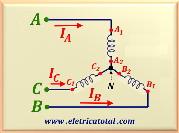
We can define a three-phase transformer as a group with three single-phase transformers in which the three primary
windings and the three secondary windings operate simultaneously.
A very important aspect to ensure the proper functioning of the transformer is good efficiency in dissipating the
heat generated by it. There are several ways to dissipate the heat generated by the equipment, generally in transformers
with higher power. In this case, the windings are submerged in insulating oil, which improves heat conduction and,
when in contact with the fins, increases the efficiency of the dissipation system. In transformers with lower power,
the windings are in direct contact with the air.
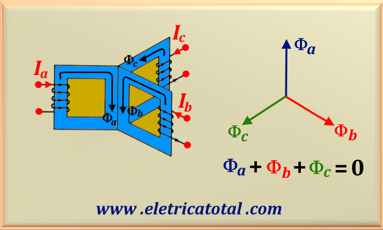
A three-phase transformer can be constructed with three primary windings and three secondary windings on a magnetic core.
Thus, they can be considered as three units, similar to a single-phase transformer, as shown in Figure 95-01.
For simplicity, only the primary windings have been represented.
Figure 95-01
Then, if a balanced three-phase sinusoidal voltage is applied to the windings, the fluxes Φa,
Φb and Φc will also be sinusoidal
and balanced. If the fluxes in each leg are added together,
the resulting net flux in the center leg will be equal to zero. Therefore, we conclude that the center leg is unnecessary.
The absence of the center leg in a transformer can result in a less efficient and less practical structure.
To solve this problem, there are two types of cores: the core type and the shell type.
Let's study each type of core separately.
For the reasons given above, it is necessary to change the construction type of a three-phase transformer.
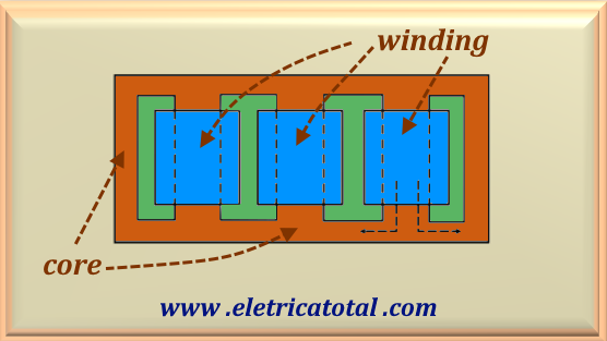
In this way, a configuration called Core Type is used, which is a flat structure used in transformers,
in which each primary and secondary winding of a phase wraps its respective core, as shown in Figure 95-02.
Figure 95-02
The core consists of silicon steel laminates and, for insulation, the laminations are coated with an oxide film on both sides.
The laminations are usually in the E and I format and are arranged in an alternating fashion to
decrease the reluctance of the magnetic path and increase the mechanical strength.
Figure 95-03
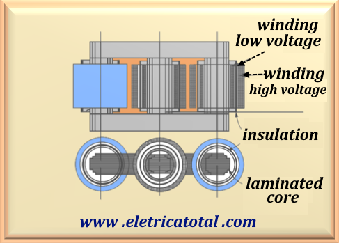
The complete cross-section of a three-phase core-type transformer with its plant is shown in Figure 95-03. This
type of transformer usually has circular cylindrical coils. The low-voltage winding is arranged closest to the core,
while the high-voltage winding is positioned above the low-voltage winding, as illustrated in the figure above.
Insulation always occurs between the core and the low-voltage winding, as well as between the low-voltage and high-voltage windings.
For transformers core-type with a large-capacity, this configuration needs to be changed slightly. In this case, the core
has three main branches, in which the windings will be housed, plus two side branches that do not have windings, as shown in Figure 95-04.
Figure 95-04
This arrangement allows the transformer to be reduced in height, while increasing its length.
This makes it easier to transport by road. In this configuration, the magnetic circuits of each phase are virtually independent.
Thus, the magnetic circuit of the three phases is slightly unbalanced, since the branches involved in the windings have a
lower reluctance than the two outer branches without windings. This results in a magnetizing current in the
intermediate branches that is slightly lower than in the outer branches. However, during operation, the magnetizing
current is so small, when compared to the line currents, that it does not cause any kind of problem.
Therefore, there are several advantages to this type of winding. Let's describe some of them:
Uniform Flux Distribution - The flat structure allows a more uniform distribution of the magnetic flux,
reducing losses in copper and iron, improving the efficiency of the transformer.
Improved Voltage Regulation - The core-type configuration helps maintain more stable voltage regulation,
even under different load conditions.
Compactação - The flat structure allows for a more compact and lightweight design, facilitating the installation
and handling of the transformer.
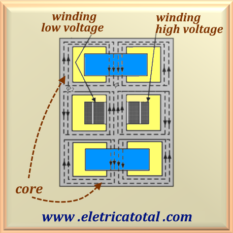
Another configuration is the so-called Shell Core, where the core construction is such that the windings are embedded in the core
rather than around the iron. The Figure 95-05 shows this configuration. The cross-sectional area of the central branches
is twice that of the side branches and horizontal branches.
Figure 95-05
The low-voltage and high-voltage windings of the three phases are wound on the central branches.
These windings are positioned vertically in the three portions, as shown in Figure 95.05. The low-voltage winding
is always placed closest to the core, and the high-voltage winding is placed above the low-voltage winding for economic reasons.
To obtain uniform distribution of flux in the core, generally
the secondary winding is placed in the central portion and is wound in the reverse direction.
Note the flux lines in the figure above.
The type of construction adopted for transformers is closely related to their intended purpose.
Some factors determine the classification, such as the primary winding voltage, operating power, operating frequency, class, etc.
The construction must ensure efficiency in removing heat from the core and windings, so that the temperature increase remains
within the limit permitted for the insulation class used.
In addition, to prevent deterioration of the insulation, moisture ingress must be prevented.
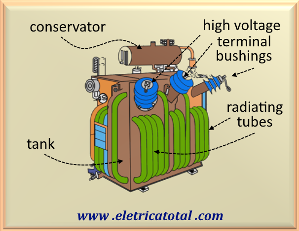
For high-power transformers, a sealed tank filled with non-flammable insulating oil is used. To facilitate the natural
circulation of the oil and increase the cooling surface exposed to the environment, tubes or fins are installed on the
outside of the tank to transfer the heat generated by the transformer to the environment.
In the case of transformers with higher power, it may be necessary to use forced ventilation or even the use of oil
pumps to force the circulation of oil through pipes, to maximize the cooling of the transformer.
Figure 95-06
High-power transformers are supplied with a so-called conservator, which is a smaller capacity tank placed on
top of the main transformer tank. The purpose of the conservator is to reduce the area of contact between the oil and
the atmosphere, minimizing rapid oxidation and, consequently, the degradation of the oil's insulating characteristics.
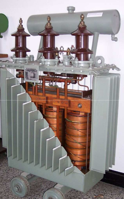
Figure 95-07
The Figure 95-07 shows a cross-section of a three-phase distribution transformer. The core of the cross-type
can be identified. At the top, we have the terminals for connecting the high-voltage primary winding, as
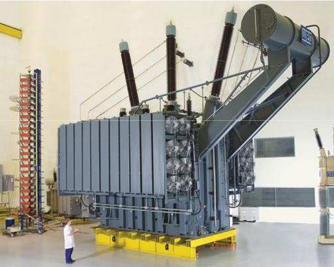
well as the conservator. High-power three-phase transformers can have considerable dimensions,
as shown in Figure 95-08.
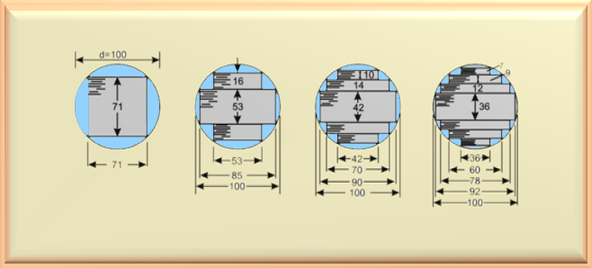
In large transformers, it is desirable for the core to be very close to a circle in shape. This makes it easier to manufacture the
coils and place them around the core. The method consists of adding iron-silicon sheets until the desired result is achieved.
However, not all of the core section will be covered by a usable magnetic flux. In Figure 95-09, on the left,
we clearly see a lot of useful space wasted when the core section is square, since the circumference of the circumscribed
circle is large in comparison with its cross section. This means that the average winding length increases, resulting in
higher energy losses and conductor costs. As we move to the right side of the figure below, the core cross-section
becomes more circular. This is achieved by increasing the number of pitches. In this way, the area of the circumscribed
circle is used more effectively.
Figure 95-09
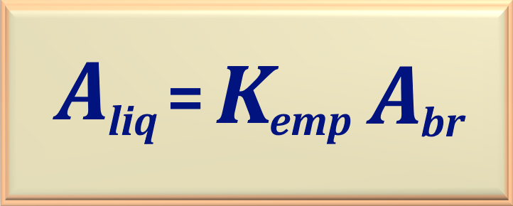
Therefore, the so-called Stacking Factor is defined, designated
by Kemp. Its value can vary between 0.70 and 0.99. A typical value
is Kemp = 0.9. Thus, we have the so-called gross cross-section (Abr)
of the core and the net cross-section (Aliq), corresponding to the part of the core cross-section
through which the magnetic flux responsible for generating the EMF flows.
The relationship between these quantities is expressed in eq. 95-01.
eq. 95-01
It is also important to note that, in order to reduce eddy current losses, the core is made up of iron-silicon sheets.
Since eddy current losses are directly proportional to the square of the sheet thickness, manufacturers try to reduce
the sheet thickness as much as possible, reducing them to the minimum possible. However, there is a practical limit
to this reduction due to mechanical constraints. This limit is in the order of 0.3 mm. Therefore, in practice,
this limit is between 0.33 mm and 0.5 mm. These laminations are isolated from each other by
a thin layer of oxide or varnish coating.
The core laminations and the insulation between the laminations reduce the effective or net core area.
The net cross-sectional area of the core is about 10% less than the gross cross-sectional area due
to the core laminations and the paper or varnish insulation.
There is another reason for choosing a circular shape for the windings. If the shape were square or
rectangular and the transformer suffered a short circuit, the high currents carried by the transformer would
cause high mechanical forces to arise that would deform the shape of the winding, tending towards a circular shape.
This would also cause the destruction of the windings and insulation. With a circular shape for the windings,
these deformations do not occur, which demonstrates why the circular shape is preferred.
It is normal for an increase in load to lead to a decrease in the supply voltage on the secondary side. However, the voltage
supplied by the transformer to the load must be kept within the prescribed limits. This can be achieved by changing the
transformer turns ratio. To make this possible, transformers have several connections at different points on the primary winding.
The transformation ratio varies between the taps, allowing different voltages to be obtained at each of them. In general,
there is a tap for the nominal voltage and others that can increase or decrease the voltage.There are derivations that allow the transformer to operate with voltages of - 2.5% and - 5% of the nominal voltage. And also with values
of + 2.5% and + 5% of the nominal voltage. In this way, it is possible to adjust the derivation so that the voltage at the load
remains within acceptable limits, according to the design.
Below, see an example of a viable derivation and its respective voltage in the case of a transformer with a primary voltage of 13,200 V.
rated voltage ☞13,200 V
rated voltage - 5%☞12,540 V
rated voltage - 2,5%☞12,870 V
rated voltage +2,5%☞13,530 V
rated voltage + 5%☞13,860 V
Therefore, the entire voltage control system is essential to meet the following specifications:
Adjust the consumer terminal voltage within the prescribed limits.
Adjust terminal voltage based on load change.
It is also possible to control both real and reactive power..
There are several reasons why taps are made on the primary winding.
Let's look at some of them.
The number of turns in the primary winding is greater than in the secondary winding. Therefore, it is easier
to fine-tune the voltage required for the transformer to function properly.
If there were taps in the secondary winding, it would be very difficult to change the taps, since the currents in the secondary are quite high.
Furthermore, the secondary windings are placed as close as possible to the core, while the primary windings are placed above
the secondary winding, facilitating tap connections.
It is also important to note that taps can be installed at the ends of the phase, at the neutral point or in the middle of the
winding of one of the phases. When taps are installed at the neutral point, the insulation between the different parts of
the transformer will be reduced. This arrangement is economical and particularly important for large transformers.
It should be noted that changes in the tap of a transformer can alter core losses, leakage reactance, copper losses and, sometimes, problems in transformer paralleling.
Basically, there are two methods for changing the tap in a transformer.
1 - Tap change with transformer no load or off.
2 - Tap change with the transformer energized or under load.
1 - No-Load Tap Change
As the name suggests, in this method, tap changing is done after disconnecting the load from the transformer.
Off-load tap changing is usually provided in transformers operating at low power and low voltage.
It is the cheapest method of tap changing as it is done manually through the handwheel installed on the transformer cover.
2 - Derivation Change with Load
On-load tap changers are used to change the turns ratio of the winding without disconnecting the load from the transformer.
The tap change can be carried out even when the transformer is supplying power to the load. With the load connected,
on-load tap changers make a significant contribution to the efficiency of the system. Nowadays, practically all large
power transformers are equipped with tap changers that operate on load.
The reason for providing on-load tap changer in power transformers is:
1 - During operation under load, the main circuit remains unchanged.
2 - Dangerous sparks are prevented from occurring. The terminations on the windings are led to
a separate oil-filled compartment where the on-load tap-changer is housed. This tap-changer is a motor-operated
selector switch that can be controlled locally or remotely.
When purchasing a transformer, there are a number of factors that must be taken into account, depending on its intended use.
So, we will list the most common ones below.
1 - Transformer power in kVA.
2 - Operating voltage, V1 and V2, with or without the presence of taps.
10 - Efficiency, power factor, impedance per unit, work location (indoor, outdoor, skid mount) ...
Note that several factors influence the purchase of a transformer. Note that, for example, the efficiency
of a transformer depends on the load and the power factor. According to ABNT
(Brazilian Association of Technical Standards), the efficiency of a transformer provided by the manufacturer must be
related to the nominal load with unity power factor. On the other hand, losses are related to the windings and the
core of the transformer. At first glance, losses may seem insignificant in relation to the nominal power of the transformer.
However, these losses are what define which is the best equipment to be purchased.
Therefore, it is not enough to simply analyze the commercial conditions of the various manufacturers when
purchasing a transformer. It is necessary to take into account the cost of losses to avoid unpleasant surprises when purchasing.
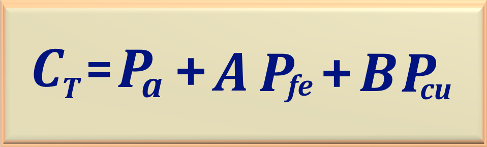
Therefore, the cost is usually assessed using the so-called capitalized price, which includes the energy
losses dissipated in the copper and ferromagnetic material of the transformer core, during a certain period of operation,
generally 10 years.
Through capitalization, it is possible to show the user the influence of transformer losses, which in turn leads to energy waste.
Therefore, it is essential to minimize the costs resulting from these losses. In general, electric power utilities have formulas that
have been developed and improved over the years.
One of the formulas used is shown in eq. 95-02.
eq. 95-02
In this equation, the meaning of the variables is:
CT - Total capitalized cost.
Pa - Purchase price of the transformer.
Pfe - Core losses (no load).
Pcu - Copper losses in windings (with load).
A - Core loss factor.
B - Copper loss factor.
This equation takes into account energy costs, interest rates, annual inflation and other economic factors,
combining the initial cost of purchasing the transformer with the operating costs over its lifetime.
As an example, let's use this equation in a practical example, adopting the following values: A = 838.70 and B = 522.20.
Suppose the acquisition of a 1,500 kVA and 69 kV/13.8 kV transformer. In Table 95-01,
we present the data from 4 suppliers.
Table 95-01
Manufacturer
Price($)
Pfe (kW)
Pcu (kW)
CT ($)
A
30,000
4.00
9.00
38,054.60
B
35,500
3.50
7.00
42,090.85
C
28,450
5.00
11.00
38,387.70
D
28,000
7.00
15.00
43,737.30
From the table, we can easily see that manufacturer D has the lowest price.
However, taking into account the losses, it has become the highest value offer. Therefore,
the offer from manufacturer A is the most advantageous when considering the losses, justifying its acquisition.
If a transformer operates at high flux density, then there will be less need for magnetic material. Therefore, from an
economic point of view, a transformer is designed to operate in the saturation region of the magnetic material of the core.
As a consequence, the excitation current is not sinusoidal, that is, this current will contain the fundamental
and all odd harmonics. However, the third harmonic is predominant and, for all practical purposes,
harmonics of order higher than three can be neglected. The percentage of the third harmonic in the nominal
voltage can vary between 5% and 10% of the fundamental. At 150% of the nominal power,
the third harmonic current can be as high as 30% to 40% of the fundamental.
In Chapter 93, we saw in more detail the phenomenon of magnetizing current nonlinearity and how this
nonlinearity generates harmonics that cause distortions in the magnetizing current. If the reader is interested,
he can access the corresponding item by clicking here ☞Excitation Current in Transformers.
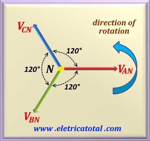
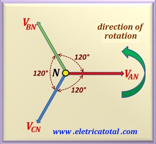
When studying three-phase systems, it is important to consider that the voltages are generated by a three-phase generator.
In this generator, we have three independent windings that are electrically out of phase with each other by 120°.
As a result, with each turn of the generator rotor, three alternating voltages called phases will be generated, which
will obviously be electrically out of phase with each other by 120°. These voltages, as in the single-phase case,
follow a sinusoidal or cosinoidal function.
The three phases produced are identified by letters of the alphabet. Nowadays, they are usually designated by the letters
A, B, C, and in older literature, the letters R, S, T were used. By default, the direction of rotation
of the phases is always in the counterclockwise direction, as shown in Figure 95-10.
Figure 95-10
Therefore, there are two possible phase sequences. One is the DIRECT sequence,
designated as the ABC sequence.
It can also be designated as BCA or CAB. We simply move the initial letter to the end. Then,
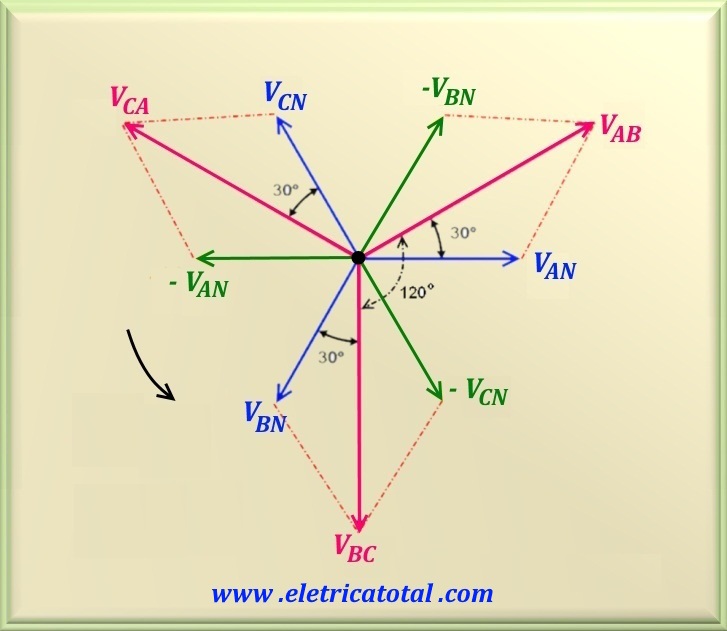
the sequence repeats. Observe Figure 95-10, where the AN phase appears as a reference (0°).
Rotating counterclockwise,
the next phase to take the place of the AN phase is the BN phase. Next, the CN phase,
completing the cycle. This is the order of the phases in the direct sequence.
Figure 95-11
Based on the above graph, it is possible to plot a new graph showing the relationship between phase voltages and line voltages,
as illustrated in Figure 95-11.
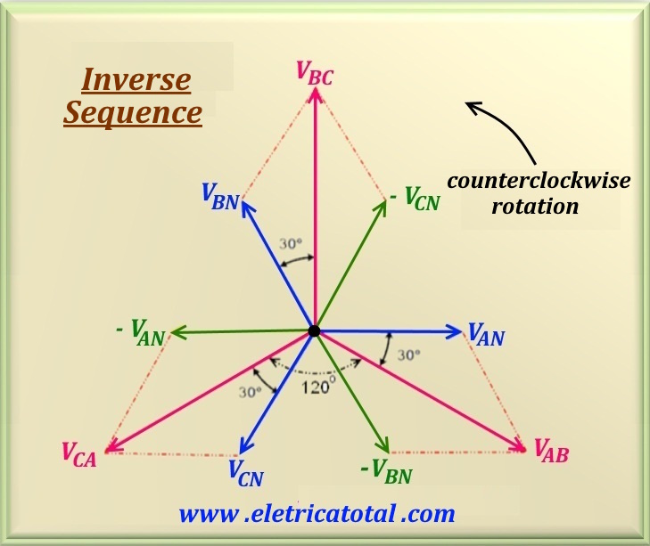
The other is the INVERSE sequence, known as the ACB sequence. It can also be CBA or BAC.
To obtain the INVERSE sequence, simply replace the B phase with the C phase and vice versa,
as shown in Figure 95-12. The direction of rotation remains counterclockwise.
Figure 95-12
Similarly, for the inverse sequence, it is possible to graphically represent the relationship between the
phase and line voltages, as shown in Figure 95-13.
Figure 95-13
Observe the graphs shown in Figure 95-11 and Figure 95-13. We can easily conclude that in the
forward sequence, the line voltage VAB leads the phase voltage
VAN by 30°. In the case of the reverse sequence, the line voltage
VAB lags the phase voltage VAN by 30°.
Observation
"At any instant of time, the phasor sum of the three phase voltages of a three-phase generator is NULL."
The direct and inverse sequences were studied in detail in Chapter 81 and,
if the reader is interested in reviewing them, click here
☞Three-Phase Phasor.
The standard nomenclature of the phases of a three-phase transformer uses the capital letters A, B and C to represent the high voltage winding.
The low voltage winding is represented by the lowercase letters a, b and c.
Each winding has two terminals that receive the subscript 1 and 2.
The interconnection of the phase windings to generate a three-phase system must meet three possible alternative connection modes: delta connection; star connection and zig-zag connection. Each of these connections has two variations. For example:
a star connection can be made by joining the terminals A1, B1 and C1 to form the neutral terminal, leaving A2, B2 and C2 as line terminals. Alternatively, we can join A2, B2, and C2
to form the neutral, and use A1, B1, and C1 as line terminals.
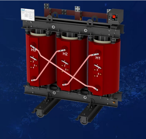
In Brazil, in distribution transformers, it is common for manufacturers to represent the high voltage terminals with the capital letter H.
Thus, we have the terminals H1, H2 and H3. And the low voltage terminals with the capital letter X, being X0, X1, X2 and X3.
In this case, the terminal X0 corresponds to the neutral. See Figure 95-14 for a photo of a distribution transformer
that illustrates the nomenclature mentioned above.
According to the standard, the H1 terminal (high voltage) is conventionally positioned to the left of the transformer,
when viewed from the low voltage side. Figure 95-14 illustrates this arrangement clearly.
Figure 95-14
Since the primary and secondary can be connected in different ways, there are at least twelve possible combinations.
According to the phase shift that exists between
the line voltages on both sides of the transformer, these combinations can be organized into four main groups,
as detailed below.
Group 1 - phase shift 0° - Notation: Yy0, Dd0 e Dz0.
Group 2 - phase shift 180° - Notation: Yy6, Dd6 e Dz6.
Group 3 - phase shift 30° lagging - Notation: Yy1, Dd1 e Dz1.
Group 4 - phase shift 30° leading - Notation: Yy11, Dd11 e Dz11.
It is worth noting that this notation is derived from the position of the hand of an analog clock. When the phase shift is 0°, it is understood that the hand is vertically pointing upwards (pointing to the number 12 - taken as a reference - "zero"). When the phase shift is 180°, it is understood that the hand is vertically pointing downwards (pointing to the number 6, 180° from the previous position - 6). And in the case of 30° behind, it is understood that the hand is pointing to the number 1 of the clock (note that the hands of the clock, when considered phasors, rotate counterclockwise). Finally, when there is an advance of 30°,
the hand is pointing to the number 11 of the clock.
Connections in transformers is a broad subject. Therefore, we decided to address this topic in a specific chapter. To access,
click here ☞Connections in Transformers.
7. Possible Connections in a TransformerThree-Phase
Most of the power generated and transmitted over long distances in a system is of the three-phase type, this is due to economic reasons. Furthermore,
since the third harmonic flux created by each winding is in phase, the preferred winding type is the shell-type , because it provides an external
path for this flux. Thus, we can state that the shell-type winding provides a voltage with a less distorted waveform than the
core-type winding.
The primaries and secondaries of any three-phase transformer can be connected independently in so-called star (Y) or delta (Δ) configurations.
This means that a three-phase transformer bank can be assembled in a total of four possible connection configurations:
1 -Star - Star(Y – Y)
2 - Delta - Delta (Δ – Δ)
3 -Star - Delta (Y – Δ)
4 - Delta - Star(Δ – Y)
These configurations have already been studied in chapter 83 - three-phase circuits, which can be
revisited in ☞Three-Phase Circuits.
For three-phase transformers, the calculations of impedance, voltage regulation, efficiency
and other similar calculations are performed taking one
phase at a time. For this, the same techniques that have already been
developed for single-phase transformers are used.
Next, we will discuss the advantages and disadvantages of the connection types in three-phase transformers.
Since most transformers are designed to operate at the knee of the magnetization curve, i.e. in the saturation zone, such designs cause the induced currents and the electromotive forces (EMFs) to be distorted. This happens because, although the magnetizing currents are still 120° out of phase with each other, their waveforms are no longer sinusoidal. Thus, if we add the currents, they will be different from zero. Therefore, if the neutral is not grounded, these currents are forced to cancel each other. As a result, they distort the EMF waveform, generating harmonics.
Thus, three-phase transformers connected in star-star are operated with grounded neutrals, that is, the neutral of the primary is directly connected to that of the power supply. If the neutral remains isolated and an unbalanced load is connected to the secondary, the electrical position of the neutral will shift, altering the magnitudes of the phase voltages. Grounding the neutral on the primary prevents this improper operating condition.
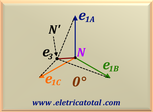
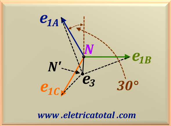
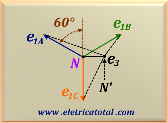
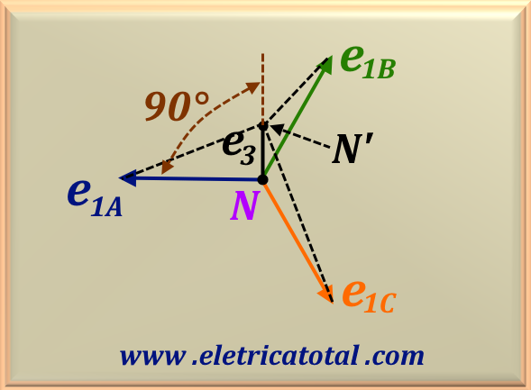
To illustrate this fact, we will consider the fundamental phasors of the balanced phase voltages. Let us call them e1A, e1B, and e1C, with each phasor having magnitude e1. The third harmonic voltage for each phase is e3. At a given moment, their relative positions are illustrated in Figure 95.10. Since the frequency of the third harmonic of the phase voltage is three times greater than the fundamental, their relative positions vary in time, shifting the position of the neutral N'. This phenomenon is known as swinging neutral. Thus, the maximum voltage in any phase is given by
e1 + e3. Figure 95-15 presents a series of illustrations of the oscillating neutral phenomenon.
Figure 95-15
Note that the voltage phasors are represented as rotating in the counterclockwise direction. For each 30° rotation,
the e3 phasor rotates three times this amount, that is, 90°. Thus, the presence of harmonics in the voltage is undesirable, as it can generate
high voltages in the winding insulation. Therefore, the use of a grounded neutral or a tertiary delta winding will allow a path
for the third harmonic of the current, thus ensuring a sinusoidal flux and a sinusoidal phase voltage.
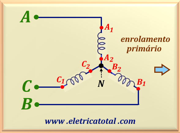
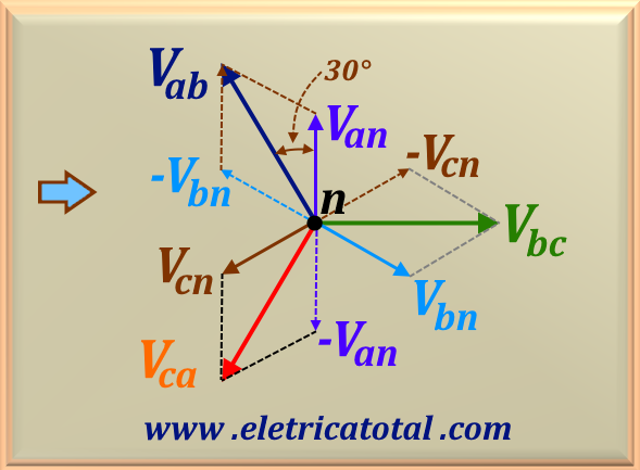
The circuit shown in Figure 95-16 is a star - star configuration for the transformer primary circuit.
Note that we have used capital letters to represent the line and phase voltages. Figure 95-17 shows the primary voltage graph.
In this configuration, the line voltage leads the phase voltage by 30°, or the phase voltage lags the line voltage by 30°. On the other hand, in terms of magnitude, the line voltage is √3 times the phase voltage.
In general, we can express the above mathematically using eq. 95-02.
eq. 95-02
We must also remember that, in a star circuit, the line current is equal to the phase current, according to eq. 95-03.
eq. 95-03
Figure 95-16Figure 95-17
Figure 95-18Figure 95-19
In figures Figure 95-18 and Figure 95-19, we represent the transformer secondary circuit and its respective phasors.
In the secondary, lowercase letters are used to represent the phasors. All considerations made for the primary are also valid for the secondary, including equations eq. 95-01 and eq. 95-02. In the study of three-phase transformer connections that will be studied in the next chapter, this configuration is called Yy0 and belongs to group 1.
This occurs because the secondary voltage points to the number 12 on the dial of an analog clock. This position is taken as a reference and represented by the number ZERO. Therefore, it is called Yy0.
The star-star connection is the most economical and has advantages and disadvantages. Let's analyze them.
Advantages of Star - Star Connection
The number of turns per phase and the amount of insulating material are minimal, since the phase voltage is 1 / √3 of the line voltage.
There is no phase shift between the primary and secondary voltages.
It is possible to connect the neutral, since the star - star configuration provides the neutral points
in both windings.
Disadvantages of Star - Star Connection
Under unbalanced load conditions on the secondary side, the load side phase voltages change unless the load neutral point is grounded. This condition is called neutral shift. However, by connecting the primary neutral point to the generator neutral point, the difficulty of neutral shift can be overcome.
The transformer primary draws a magnetizing current containing the third and fifth harmonics. If the neutral of the primary winding is not
connected to the generator neutral, the third and fifth harmonic currents will distort the central flux and alter the waveform of the output voltages.
However, by connecting the primary neutral to the generator neutral, the return path is provided for the third and fifth harmonic currents and thus
the problem of voltage distortion is overcome.
Even if the primary neutral point is connected to the generator neutral or grounded, the third harmonic may still exist. This will appear on
the secondary side. Although secondary line voltages do not contain third harmonic voltages, the 3rd harmonic voltages are additive at the
neutral and cause triple frequency neutral current (3rd harmonic) that will cause interference in the nearby communication system.
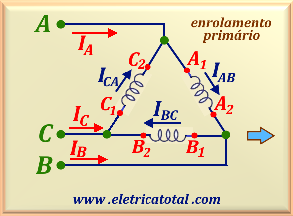
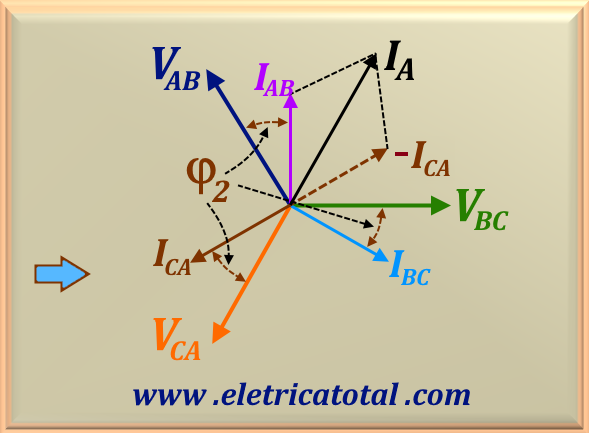
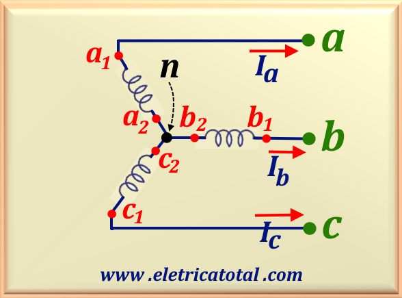
In the following figures, the phase currents in the primary winding are represented by IAB,
IBC and ICA
while the line currents are represented by IA, IB and
IC.
In the secondary winding, the phase currents are represented by Iba, Icb and
Iac, and the line currents are represented by Ia, Ib and
Ic.
Note that the angle φ2 in the figures below represents the load angle. In other words,
φ2 represents
the load power factor or the phase shift between the transformer's nominal voltage and the phase current. Furthermore, it can be seen that there is no
phase difference between the primary and secondary voltages. For this reason, the connection is called Dd0 and belongs to group 1.
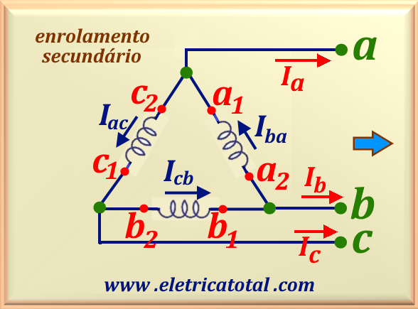
Figure 95-20Figure 95-21
Figure 95-22Figure 95-23
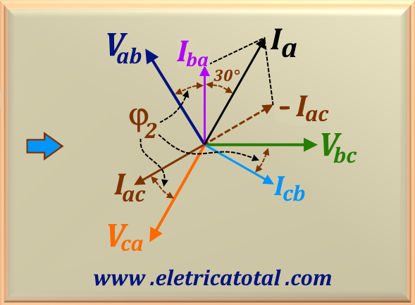
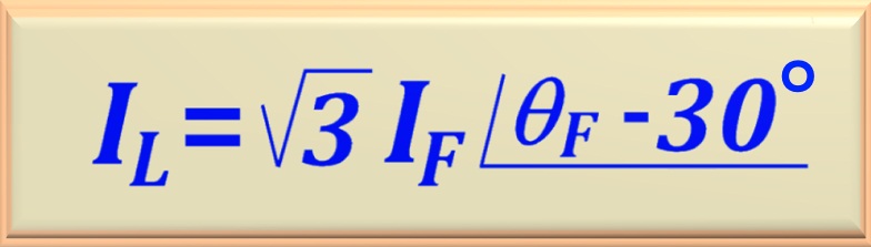
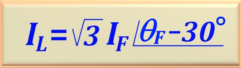
In this configuration, after calculating the phase current, we can find the line current by multiplying the magnitude of the phase current by √3 and subtracting 30° from its angle. Mathematically, this can be expressed
using eq. 95-04.
eq. 95-04
In this equation, θF represents the phase current angle, and by subtracting 30° from it, we find the line current angle.
From the graph in Figure 95-23 and the circuit shown in Figure 95-22, we can write that:
Ia = Iba - Iac
Ib = Icb - Iba
Ic = Iac - Icb
In this configuration, the components of the third harmonic of the current of the three phases are out of phase with each other by 120°, totaling 360°. Thus, these harmonics are in phase and circulate in the delta winding of the primary. This current produces a sinusoidal flux, resulting in a sinusoidal voltage in the secondary.
This configuration is used in power systems where large currents and low voltages are used.
In addition, this connection is suitable when continuity of service is required,
even if one of the phases presents a fault. When operated in this way, the transformer
provides three-phase currents and voltages with the correct phase, but its capacity
is reduced to 57.7% of the nominal capacity.
Advantages of Delta - Delta Connection
In this configuration, there is no phase shift between the primary and secondary voltages.
There is no distortion in the magnetic flux, since the third harmonic components of the magnetizing current flow through the delta connection windings of the primary winding. Thus, the third harmonic does not flow in the line currents.
Since the phase current is 1 / √3 times smaller than the line currents, the diameter (or gauge) of the winding conductors is reduced, generating lower costs.
This type of connection does not present operational problems, even if the load on the secondary is unbalanced.
Disadvantages of Delta - Delta Connection
The amount of insulating material is greater than in the star - star configuration,
since the phase voltage and line voltage are equal.
Another problem with this configuration is the absence of a neutral terminal.
Typically, this configuration is used when it is desired to reduce line voltage, such as at the receiving end of a transmission line.
In this connection, the primary's neutral is grounded.
Figure 95-24Figure 95-25
Figure 95-26Figure 95-27
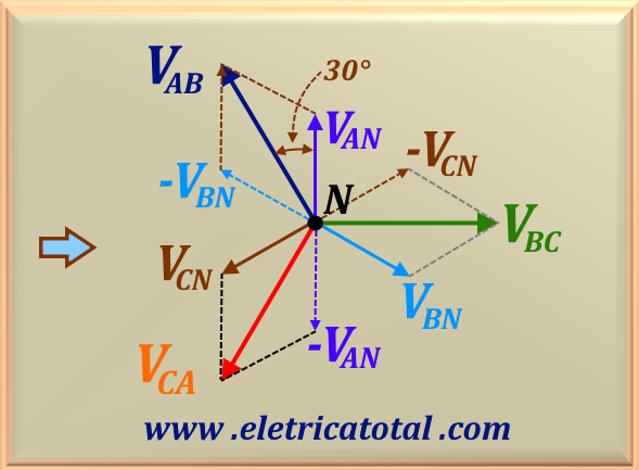
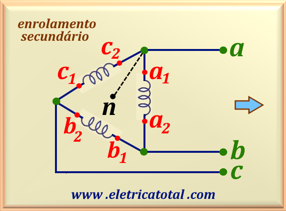
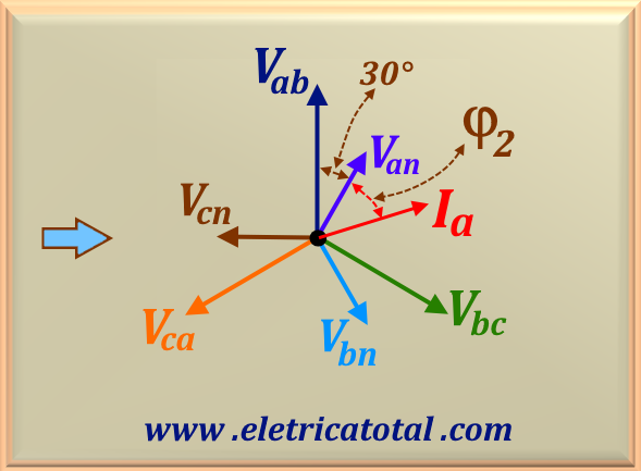
As shown in Figure 95-25 and Figure 95-27, it can be seen that the secondary line voltage lags 30° behind the primary line voltage. The same is true for the primary and secondary phase voltages. For this reason, this configuration is called Yd1. In Figure 95-27, it can be seen that the phasor of the voltage Van points to the number 1 on the dial of an analog clock. Hence the name Yd1. This configuration belongs to group 3.
The third harmonic currents flow within the mesh provided by the delta connection,
generating a sinusoidal waveform.
Therefore, there are no distortion problems in the output waveform, resulting in a sinusoidal waveform.
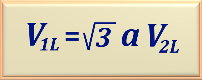
In this configuration, we can establish a relationship between the primary line voltage and the secondary line voltage. Designating V1L for the primary line voltage and V2L for the secondary line voltage, and considering that "a" is the transformer transformation ratio, we obtain eq. 95-05.
eq. 95-05
Advantages of Star - Delta Connection
This type of connection does not present problems with third harmonic components, since they are suppressed by a current that circulates in the delta connection of the secondary.
This connection is quite stable in relation to unbalanced loads, since the delta connection of the secondary partially redistributes any imbalance that may occur.
It is possible to provide a neutral connection on the primary.
On the high voltage side of the transformer, the insulation system supports 57.7% of the line voltage.
Therefore, there is a reduction in the cost of transformer insulation.
Disadvantages of Star - Delta Connection
Because this connection introduces a phase shift between the secondary voltage and the primary voltage of the transformer, this can cause problems when the secondaries of two transformer banks are placed in parallel.
The secondary voltage will lag 30° behind the primary voltage if the phase sequence is direct or ABC. And it will be early if the sequence is reverse or ACB.
The use of this type of connection allows the neutral of the transformer secondary to be connected to earth. It is quite popular as distribution transformers when it is necessary to reduce the voltage for domestic or commercial use.
The grounded neutral contributes to the safety of the distribution system and constitutes a 4-wire system. In this way,
this system can supply three-phase equipment, using the three lines (ABC), as well as single-phase systems.
Using one of the three available lines and the neutral, we can form a single-phase system. Thus, it is possible to supply single-phase equipment such as
fans, lighting, radios, televisions, computers, etc.
This configuration is also not affected by third harmonics, since the delta connection of the primary suppresses third harmonic currents.
Figure 95-28Figure 95-29
Figure 95-30Figure 95-31
Comparing the graphs shown in Figure 95-29 and Figure 95-31, we can easily see that the secondary line voltage is 30° ahead of the primary line voltage. In particular, in the graph in Figure 95-31, we can see that the phase voltage phasor, Van, is pointing to the number 11 on the face of an analog clock. Therefore, this configuration is known as Dy11, belonging to group 4.
On the other hand, it can be seen that the relationship between the line voltage and the phase voltage for the secondary is given by eq. 95-06.
eq. 95-06
Advantages of Delta - StarConnection
This type of connection does not present problems with the third harmonic component, since it is suppressed by a current that
circulates in the delta connection of the primary.
It is a very stable connection in relation to unbalanced loads, since the star connection of the secondary with the
grounded neutral ensures operating stability.
On the high voltage side of the transformer, the insulation system supports 57.7% of the line voltage.
Therefore, there is a saving in the cost of transformer insulation.
Disadvantages of Delta - Star Connection
In this type of connection, the secondary line voltage is √3 times the transformation ratio.
The secondary line voltage leads the primary line voltage by 30°.
Observation
"Transformers connected in Star - Delta or Delta - Star configurations cannot operate in
parallel with transformers connected in Star - Star or Delta - Delta
even if the voltage ratios are adjusted correctly, since there will be a 30° phase difference between
the corresponding secondary voltages."
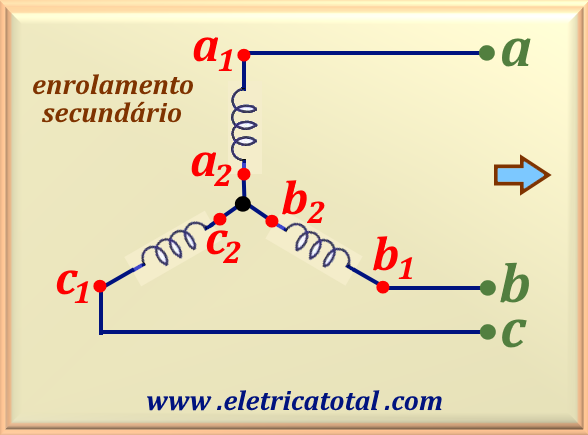
To enable the zig - zag connection, it is essential that each winding of the transformer secondary be divided into two halves.
Assuming phase A, the name that both halves of the secondary will receive will be: one of the windings will receive
the name a1 - a2; the other half will be called a3 - a4.
The name of the other two windings follows the same reasoning, that is: b1 - b2 and
b3 - b4; the other winding will be c1 - c2 and
c3 - c4.
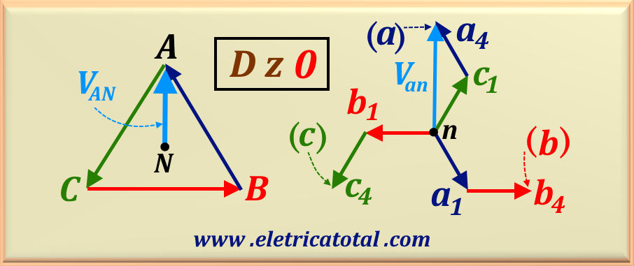
Thus, each leg of the star connection is formed using the halves of two different phases. Figure 95-32 shows the formation of a Zero Delta-Zigzag connection, designated as Dz0. It is designated zero because the phasors VAN and
Van are in phase, that is, the phase shift angle is 0°. Note that, in the figure, the phasors represented in red
have the same direction. The same occurs for the other two colors. It can be seen that the halves that are connected to the neutral (n) of the secondary are in phase opposition (180°) in relation to the corresponding line voltage of the primary.
Figura 95-32
In addition to this connection, there are the Dz6, Yz1 and Yz11. These connections are studied in more detail in chapter 96, corresponding to the study of Connections in Transformers. If the reader is interested, access ☞Zig - Zag Connection
In practice, transformers with a Zig - Zag connection are used to create the missing grounding in an ungrounded three-phase system by providing a path for the neutral to ground. Nowadays, with the large production of wind and solar energy, electric utilities are requiring the installation of grounding transformers at their points of connection to the system in order to provide a grounding reference point. Zig - Zag transformers, which have low impedance, can provide a path for zero-sequence components under fault conditions and prevent the system voltage from rising on the unfaulted phases, making the Zig - Zag transformer an excellent grounding transformer. If current limiting is required during the fault condition, a suitable neutral earthing resistor can be added to the system.
The Zig - Zag connection is also used in power systems to capture triple harmonic currents (3rd, 9th, 15th, etc.).
In this case, Zig - Zag units are installed near loads that produce large triple harmonic currents. The windings capture the harmonic currents and prevent them from propagating upstream, where they can produce undesirable effects.
For rectifying alternating current to direct current, Zig - Zag transformers offer excellent
performance, since the currents in the two halves of the winding on each leg of the core flow in opposite directions,
avoiding saturation of the transformer core.
8. Mathematics of Connections in TransformersTrifásicos
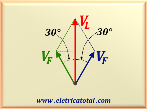
Before we begin discussing the mathematical details of three-phase transformer connections, let us clarify the relationship between the magnitudes of the line voltage and the phase voltage. Let us refer to the graph shown in Figure 95-33.
Figure 95-33
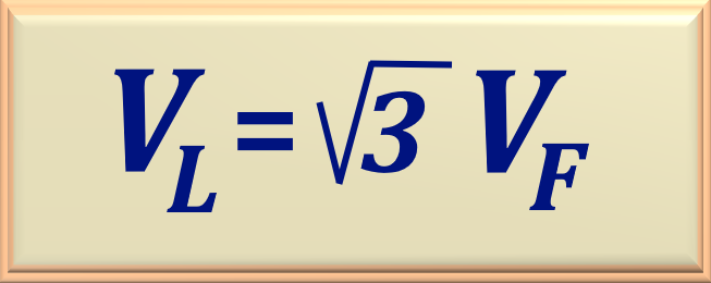
From the graph shown, we easily conclude that the line voltage is the phasor sum of the two phase voltages, which are 30° out of phase with respect to the line voltage (compare with Figure 95-25). Then, we can write:
VL = VF cos 30° + VF cos 30° = VF (√3/2 + √3/2)
Thus, performing the appropriate mathematical operation, we obtain:
eq. 95-07
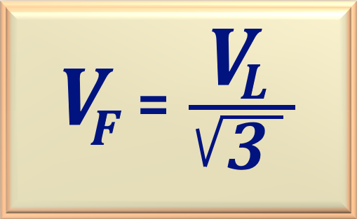
So, naturally, from this equation we can conclude that:
eq. 95-08
It is worth noting that, in single-phase transformers, the transformation ratio "a" is always a real number and is calculated by the ratio between the phase voltages. However, in three-phase transformers, the transformation ratio
can be complex, involving a phase variation and can take the following form:
V1 / V2 = a = |a| ∠θ
eq. 95-09
Let us consider, as an example, the three-phase transformer as ideal. Then, it is possible to write that the apparent power of the primary is equal to the apparent power of the secondary, that is, S1 = S2. Remembering the apparent power equation, we have the following relationship for a three-phase transformer:
3 V1 I1* = 3 V2 I2*
eq. 95-10
Where I1* and I2* represent the complex conjugate of the primary and secondary currents, as established by the apparent power equation. Then, writing the relationship between the currents, we obtain:
I1 / I2 = V2* / V1* =
1 / a* = ( 1 / |a| ) ∠θ
eq. 95-11
Now, comparing eq. 95-09 with eq. 95-11, we can conclude that:
∠ (I1 / I2) = ∠ (V2 / V1) = ∠θ
eq. 95-12
Therefore, we can write that:
"A three-phase transformer introduces the same phase shift in both the current and the electrical voltage."
After these clarifications, we can move on to studying the mathematics of connections.
In the star-star connection, there is no phase shift between the line and phase voltages, as shown in the graphs in
Figure 95-17 and Figure 95-19, repeated below for greater understanding.
Figura 95-17Figura 95-19
Thus, in this connection, for the line and phase voltages, the equations studied in item 8 and repeated below are valid.
eq. 95-07
So, naturally, from this equation we can conclude that:
eq. 95-08
It should be noted that in this connection the line and phase currents, both primary and secondary, are iguals.
And the primary current and the secondary current are related by the transformation ratio, "a",
according to eq. 91-03, studied in Chapter 91 and repeated below.
In a Delta - Delta connection, the line and phase voltages are the same. Therefore, there is no phase shift between them. The
Figure 95-21 and Figure 95-23, repeated below, clearly show this.
Figure 95-21Figure 95-23
Regarding the currents, the graphs show that the line current, both in the primary and secondary, lags 30° behind the phase current.
In terms of magnitude, the line current is the phasor sum of two phase currents. Thus, it will be √3 times greater
than the phase current (the same case shown in Figure 95-33). If the phase current has an angle θF, then eq. 95-04, studied in item 7.2, is valid.
eq. 95-04
And the primary current and secondary current, both line and phase, are related by the transformation ratio, "a",
according to eq. 91-03, studied in Chapter 91 and repeated below.
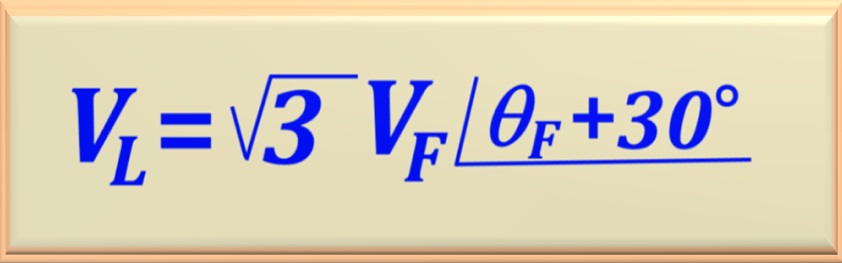
In a Star - Delta connection, both the primary and secondary have a line voltage that is 30° ahead of the phase voltage. And the primary phase voltage also leads the secondary phase voltage by 30°. The Figure 95-25 and Figure 95-27, repeated below, clearly show this.
Figure 95-25Figure 95-27
Mathematically, the above can be written as eq. 95-13. Note that this phase difference becomes relevant when another transformer is placed in parallel. In this case, attention must be paid to this phase shift.
eq. 95-13
On the other hand, the Star - Delta connection does not present any problem regarding the
sequence zero (component DC and harmonics multiples of 3).
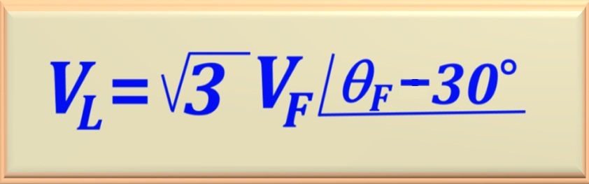
In the Delta - Star connection, both the primary and secondary line voltage lags the phase voltage by 30°. And the primary phase voltage also lags the secondary phase voltage by 30°. Note that the primary line current also lags the secondary line current by 30°. The Figure 95-29 and Figure 95-31, repeated below, clearly show this.
Figure 95-29Figure 95-31
Mathematically, the above can be written as eq. 95-14. Note that this phase difference becomes relevant when another transformer is placed in parallel. In this case, attention must be paid to this phase shift.
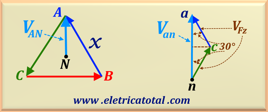
Our goal is to calculate the secondary phase voltage of the zig-zag connection, as well as the line voltage.
These values must be referenced to the primary line voltage by means of the transformation ratio.
First, we will calculate the phase voltage based on the diagram shown previously in Figure 95-32.
The Figure 95-34 shows a "zoom-in" of the phase voltage, represented by Van.
Observing the angle of 30° between the phasors, it is possible to write the value of Van as
the sum of the projection of the phasors Vcn and Vca onto it. Since, in terms of magnitude,
Vcn = Vca, then let us make
Vcn = Vca = VFz, where VFz represents the phase voltage of the zig - zag configuration.
Figura 95-34
Van = VFz cos 30° + VFz cos 30° = VF (√3/2 + √3/2)
Performing the calculation, we obtain:
Van = √3 VFz
eq. 95-15
Considering the transformation ratio "a" of the transformer, we can find the relationship between the phase voltage of the secondary of the zig - zag connection, represented by Van, and the phase voltage of the primary of the delta circuit, represented by
VAN.
VAN = a Van = √3 a VFz
eq. 95-16
Now let's calculate the relationship between the line voltage of the primary, for example, VAB, and the phase voltage of the secondary of the delta circuit, represented by
VAN. We will represent the line voltage of the primary in the delta connection as VLΔ.
Since in a delta connection we know the relationship between line voltage and phase voltage, given by
VLΔ = √3 VFΔ = √3 VAN, we can write that:
VLΔ = 3 a VFz
eq. 95-17
Considering a = 1, we easily conclude that the line voltage of the delta connection is equal to three times the phase
voltage of the zig - zag connection.
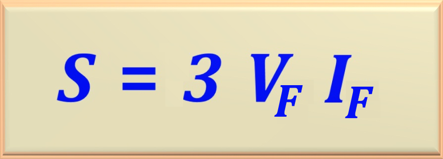
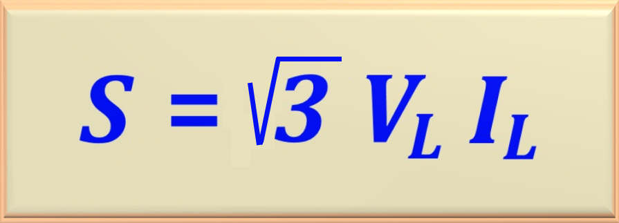
One possible approach to calculating the power in a three-phase transformer is to consider it as a set of three single-phase
transformers connected in the appropriate manner. We know that in a single-phase transformer, the apparent power is the product
of the applied voltage (VF) and the current (IF) that flows through the transformer
winding. Since we have three single-phase transformers, to find the total power, simply multiply the power of each transformer
by 3 (three). Thus, we can write eq. 95-18 below.
eq. 95-18
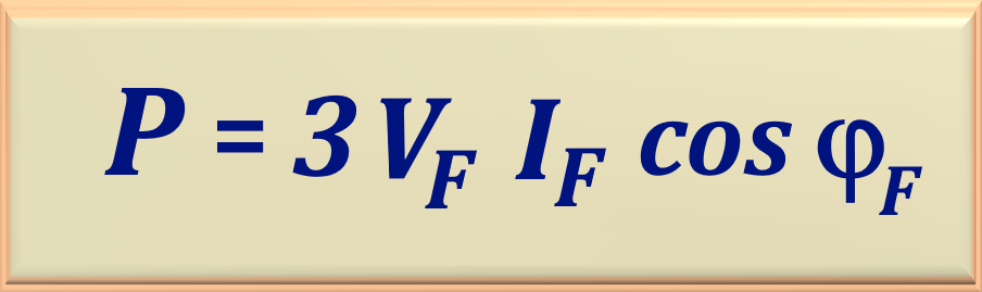
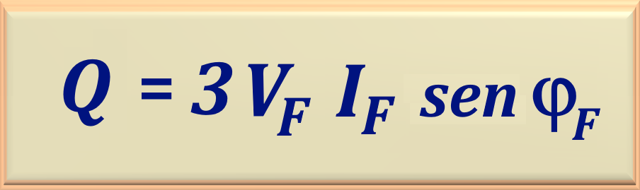
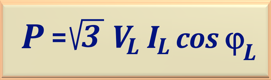
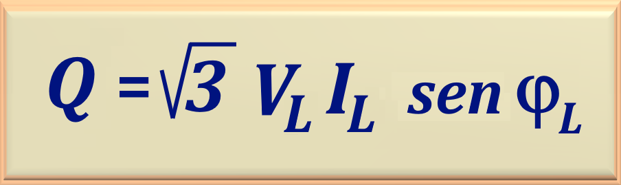
Since we know the equation that defines apparent power, we can establish the equations for real or
effective power and reactive power. To do this, simply determine the phase shift angle between the
voltage and the current, represented by φF. In this way, we arrive at the equations
eq. 95-19 and eq. 95-20, presented below.
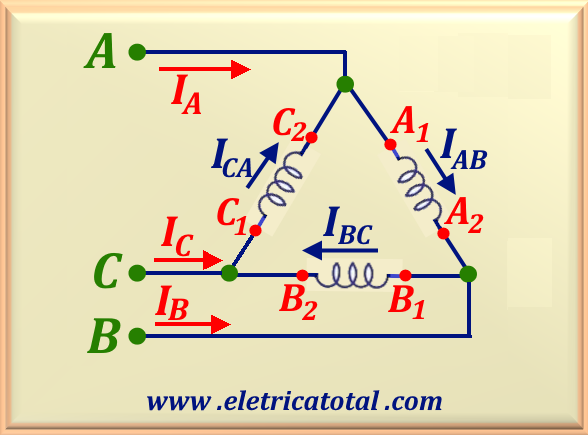
Let's analyze a three-phase transformer in delta connection, as shown in Figure 95-35 below.
Figura 95-35
We know that in this connection the line voltage ( VL = VAB = VBC = VCA )
is equal to the phase voltage ( VF = VAB = VBC = VCA ). And the phase current ( IF = IAB = IBC = ICA )
is √3 smaller than the line current
( IL = IA = IB = IC ).
Thus, applying these relations in eq. 95-15, we obtain:
S = 3 x VL x IL / √3
Performing the calculation, we obtain the following eq. 95-21.
eq. 95-21
As previously shown, from the apparent power equation, we can determine the real or effective
power and the reactive power by using the line voltage and line current. This calculation
follows the equations 95-22 and 95-23, presented below. Note that φL
represents the phase shift angle between the line voltage and the line current.
Let's analyze a three-phase transformer in Star connection, as shown in Figure 95-36 below.
Figura 95-36
We know that in this connection the line current ( IL )
is equal to the phase current ( IF ). And the phase voltage ( VF = VAN = VBN = VCN )
is √3 less than the line voltage
( VL = VAB = VBC = VCA ).
Thus, applying these relations in eq. 95-15, we obtain:
S = 3 x IL x VL / √3
Performing the calculation, we obtain eq. 95-21, which is the same equation as the circuit connected in delta.
eq. 95-21
Naturally, in this configuration, the equations eq. 95-22 and eq. 95-23 are also valid for calculating
the real or effective power and the reactive power.
Conclusion
" No matter what the connection configuration, the apparent power of the three-phase transformer is given by eq. 95-21."