2 - Factors that Determine Parallel Transformers
click here!
3 - Parallelism Conditions for Three-Phase Transformers
click here!
4 - Calculation of Shared Load Between Two Three-Phase Transformers in Parallel
click here!
Podemos destacar três razões para o uso de transformadores em paralelo.
If this condition is not exactly met, that is, assuming two transformers A and B that present a
difference in their voltage or transformation ratios, parallel operation is still possible.
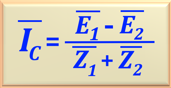
By applying the same primary voltage to the transformers in parallel and, since the transformation ratios are unequal, the
EMFs in the secondary windings will not be equal. Due to this inequality of EMFs induced in the
secondary windings, there will be, even without load, a circulating current flowing from one secondary winding
(with higher induced EMF) to the other secondary windings (with lower induced EMF). In other
words, there will be circulating currents between the secondary windings and, consequently, also between the
primary windings when the secondary terminals are connected in parallel.
The impedance of transformers is small, so that a small percentage difference in voltage may be sufficient to circulate a
considerable current and cause additional loss of I2R. When the load is applied to the secondary
side of such a transformer combination, the circulating current will tend to produce unequal loading conditions on the
transformers. Therefore, it may be impossible to supply the load at the output of the parallel-connected group without
one of the transformers becoming excessively hot. Ignoring this fact may result in problems such as short circuits,
overloads and inefficient operation, compromising the reliability and safety of the system.
Case 1 - When two transformers have the same transformation ratio and the voltages in
the impedance triangle are identical in magnitude and shape.
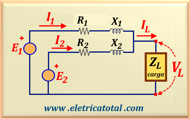
The requirements of the above conditions are known as ideal condition or ideal case. Figure 97-01
shows the equivalent circuit of the two transformers in parallel.
Case 2 - When two transformers have the same transformation ratio but different
voltage triangles.
In this case, when there is no load, the voltage in both secondaries has the same module and the same
phase, that is, the phase difference between E1 and E2 is
zero. However, this is only possible if the values of the magnetizing currents of the two
transformers are very close. Under these conditions, it is possible to connect the two transformers in parallel,
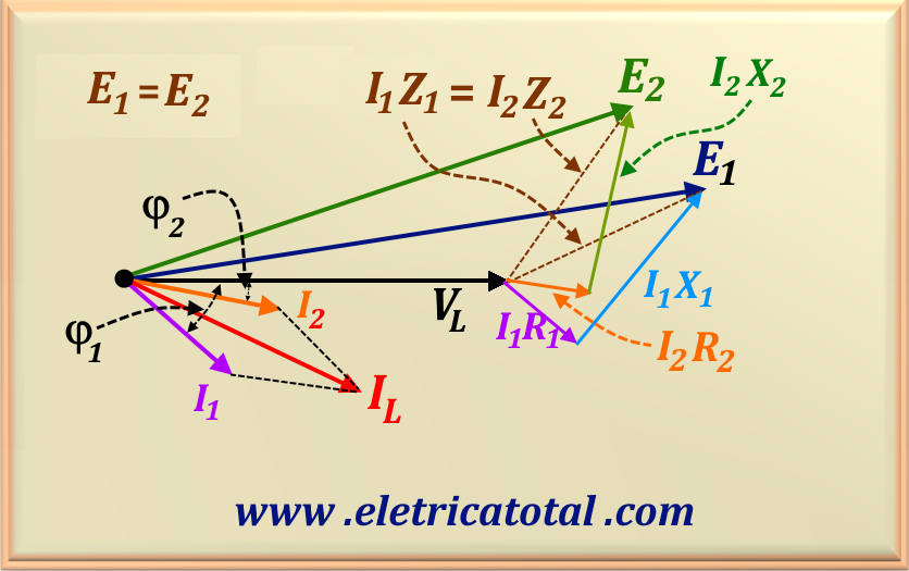
since, in the absence of load, no current will flow between the windings. Figure 97-03 shows the diagram
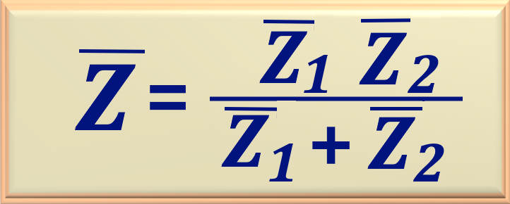
of the equivalent circuit illustrated in Figure 97-01, in which the transformers connected in parallel are
sharing the load current, IL, representing two impedances in parallel.
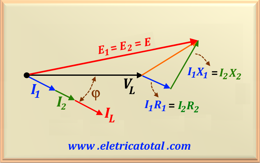
The voltage triangle over impedances is represented by two triangles: one is formed by the legs
I1 R1 and I1 X1, with the hypotenuse being
I1 Z1; the other is formed by the legs I2 R2
and I2 X2, with the hypotenuse being I2 Z2.
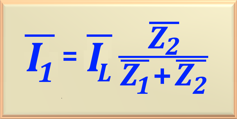
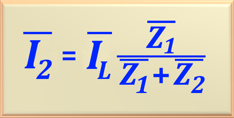
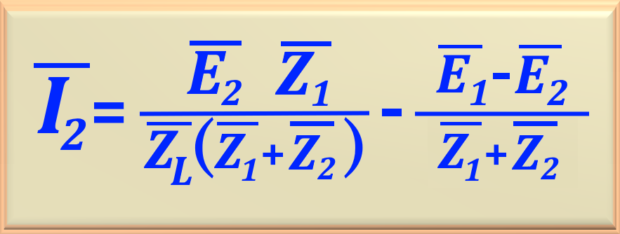
Note that in this case, the currents I1 and I2 are not in phase with each
other or with IL, since Z1 is different from Z2.
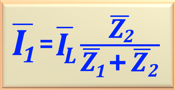
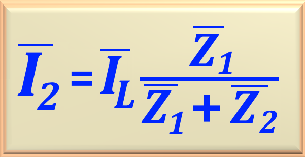
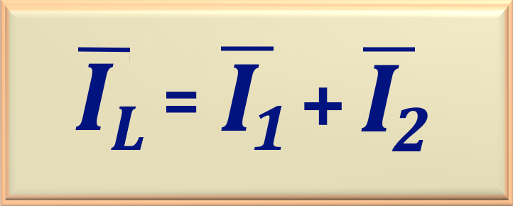
Also, IL is the phasor sum of
I1 and I2, according to eq. 97-05 below.
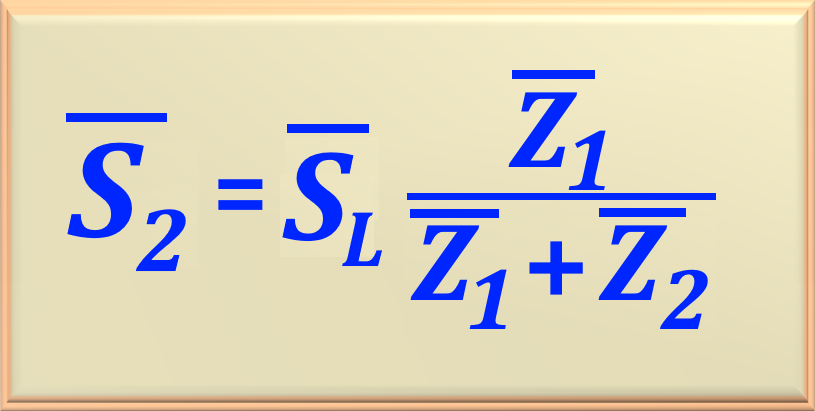
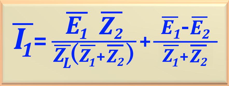
Caso 3 - When the two transformers have different transformation ratios and different voltage triangles.