Problem 65-5
Source:
Problem elaborated by the author of the site.
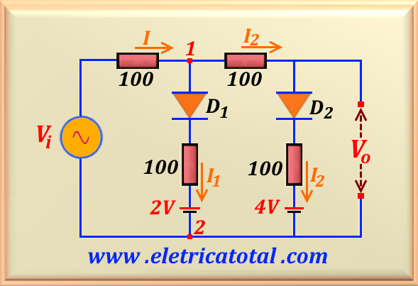
Let be the circuit shown in the Figura 65-05.1. Assume that Vi = 15 sin 1000 t and VD = 0.7 volts on the conduction. Calculate the voltage Vo and sketch a graph with the circuit transfer characteristic.
Figura 65-05.1
Solution of the Problem 65-5
For the positive part of the sine, this circuit will respond in three different ways, depending on the input voltage. So let's look at each situation separately.
When the input voltage, Vi, begins to grow its value towards the positive peak, note that while Vi ≤ +2.7, there will be no current flow through the two circuits containing the D1 and D2 diodes. So the output voltage is exactly the same as the input voltage, that is:
If 0 ≤ Vi ≤ + 2.7 V
⇒ Vo = Vi
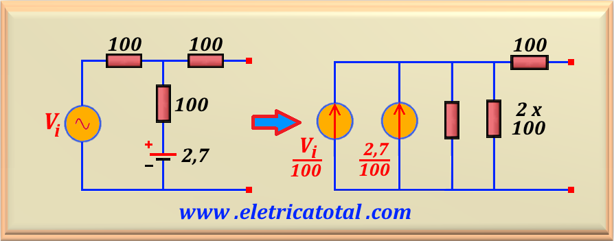
When the input voltage ranges between +2.7 < Vi ≤ +4.7, the circuit containing the diode D1 will go into conduction, but the circuit containing D2 will continue to be cut off in this voltage range and we can disregard it. Then we can use a circuit solving technique by replacing the diode conduction voltage with a battery voltage of 0.7 V . Thus, representing the diode D1 as a constant voltage source of 0.7 V, we can add its value to the battery of 2 volts, resulting in a single voltage source of 2.7 volts. Thus, we obtain the equivalent circuit shown on the left, in the Figure 65-05.2. Performing a transformation of sources in the circuit, in the end we obtain the circuit represented in the figure on the right.
Figure 65-05.2Figure 65-05.3
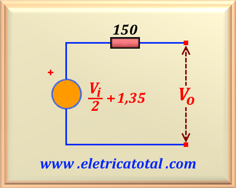
To get to the final circuit (right) we add the two current sources and calculate the parallel of the two resistors of 100 Ω each. We find a source of value (V i + 2.7) / 100 and an equivalent resistance of 50 Ω. Multiplying the value of the current source by the equivalent resistance, we find the value of the voltage source. And we add the equivalent resistance with that of
100 Ω resulting 150 Ω. This circuit is exactly the Thévenin equivalent of the circuit shown in Figure 65-05.3. Since the circuit does not have a load connected to the output, then the calculated voltage appears fully on the output. Like this:
If 2.7 < Vi ≤ + 4.7 V
⇒ Vo = 0.5 Vi + 1.35
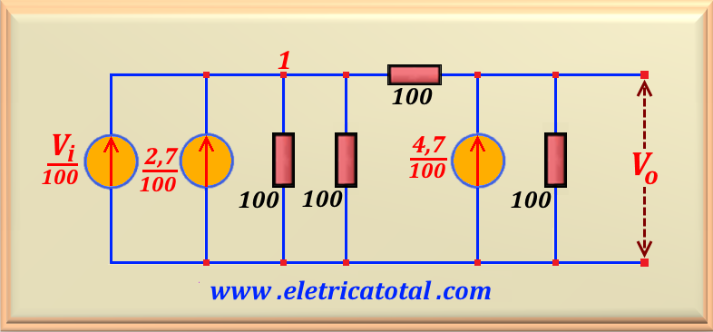
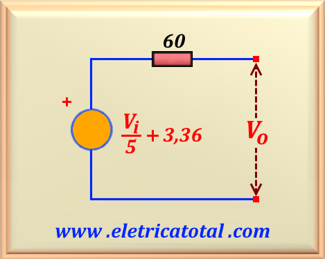
When the input voltage is greater than 4.7 volts, the circuit containing the D2 diode will operate because the diode starts to conduct. Then, using the same circuit solution technique as before, we can calculate the equivalent circuit of the entire circuit. This appears in the
Figure 65-05.4. Solving this circuit, we find the final circuit represented in the
Figure 65-05.5.
Figure 65-05.4Figure 65-05.5
To reach the final circuit we perform the same steps as above. Since the circuit does not have a load connected to the output, then the calculated voltage appears fully on the output. Like this:
If 4.7 < Vi ≤ + 15 V
⇒ Vo = 0.2 Vi + 3.36
Now, looking at the situation when the input voltage is in the negative part of the sine, it is clear
from the circuit of Figure 65-05.1 that the two diodes will be at cutting zone. Therefore,
we conclude that the two circuits containing the diodes will be inoperative. Thus we can disregard them and
the output voltage exactly follows the input voltage. So we can write that:
If 0 ≥ Vi ≥ - 15 V
⇒ Vo = Vi
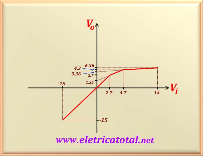
Figure 65-05.6
In the Figure 65-05.6 we show the transfer characteristic of the circuit. Notice how there is "compression" in the output relative to the input signal. In the graph, for a real diode, the slope change of the lines should be smoothed. As we are using the model of an ideal diode is worth the above representation. Note that by changing the voltage value of the batteries, you can control how much compression we want and at what points. It is also possible to increase the number of circuits and to achieve very high compression rates. It is noteworthy that this circuit only produces this compression for the positive part of the sinusoid. Of course we can get to the negative part by simply inverting the circuits containing the diodes. See the next problem.
Practical Addendum
You may be wondering where to use a circuit with these characteristics. There are numerous practical applications. But let's cite an application where, of course, everyone has "listened", meaning it is widely used in distorting circuitry for the electric guitar in the music industry. Numerous bands use this feature, such as Van Hallen, Santana, Dire Straits, etc ... In some types of equipment that use this circuit, it is possible to vary the compression rate by producing electronic devices known in the music world as fuzz pedal, overdrives pedal, etc ... Of course, this circuit
it is a simplified model. In practice, we add operational amplifiers to make the circuit more efficient.