Problem 65-3
Source:
Problem elaborated by the author of the site.
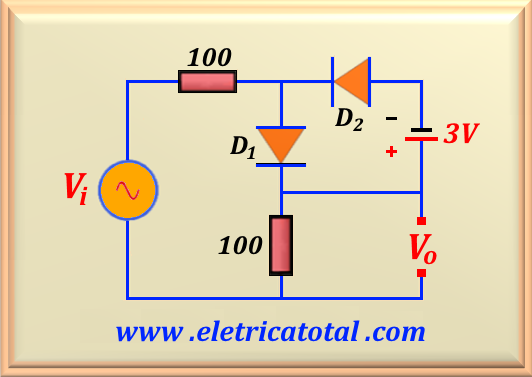
Given the circuit shown in the Figure 65-03.1, calculate the output voltage Vo, assuming that the input voltage is given by Vi = 10 sin 1000 t. Sketch the waveform of Vo. Consider the voltage on the conduction diode as VD = 0.7 V.
Figure 65-0-3.1
Solution of the Problem 65-3
When the input voltage Vi initiates the growth of its value towards the positive peak,
we already know in advance that the diode D2 will remain cut across the positive portion of
the input voltage. On the other hand, the D1 diode will not conduct until the input voltage
reaches the value of 0.7 V. From that moment, the current that circulates through the diode and the two resistors is given by:
I = (Vi - 0.7 ) / (100 + 100 )
And as the output voltage Vo is given by Vo = 100 I, so we easily conclude that:
Therefore, the correct answer for the positive part of the sinusoid is:
If 0 ≤ Vi ≤ + 0.7 V
⇒ Vo = 0 V
If Vi > + 0.7 V
⇒ Vo = 0,5 (Vi - 0.7 ) V
Now let's look at what happens to the negative part of the sinusoid. Note that D1
will always be cut-off. So the circuit will work for the negative part of the sinusoid as if it didn't exist.
So the circuit comes down to the voltage source Vi, the two resistors, the 3V battery
and the D diode 2. Due to the presence of the 3V battery, it is clear that the diode
will not conducting while Vi ≥ - 3.7 V. As soon as the input voltage reaches - 3.7 V
and continue until it reaches the peak value, that is, - 10 V , the diode D2 is conducting.
Then we can calculate the value of I by making the mesh:
Vi - 200 I + 3 + VD = 0
Algebraically working this equation and knowing that VD = 0.7 V, we get:
I = (Vi + 3.7 ) / (100 + 100)
However, we know from the circuit that Vo = - 100 I. So replacing we have:
Vo = - 0.5 (Vi + 3.7 )
Therefore, the correct answer for the negative part of the sinusoid is:
If - 3.7 ≤ Vi ≤ 0 V
⇒ Vo = 0 V
If Vi < - 3.7 V
⇒ Vo = - 0.5 (Vi + 3.7 ) V
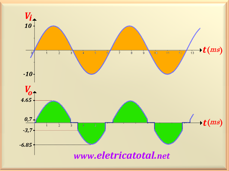
Figure 65-03.2
In the Figure 65-03.2 we see the graph of the input voltage and the output voltage. Note that next to
t = 0 there is a jump in output voltage from zero to 0.7 V. This is due to the need for a
voltage of 0. V over the diode to enter the conduction zone. For the negative part of the input voltage,
the diode only conducts when the input voltage reaches the value of - 3,7 V.
Note that there is a range in the input voltage value that generates a null output voltage and is perfectly
visible in the graph above. So we can write that:
If - 3.7 V ≤ Vi ≤ + 0.7 V
⇒ Vo = 0 V
Could you tell what would happen to the circuit if the polarity of the 3V battery were reversed?