Problem 15-20 Source:
Problem 38 - List of
Electric Circuit exercises I - School of Engineering - UFRGS - 2011 -
Prof. doctor Valner Brusamarello.
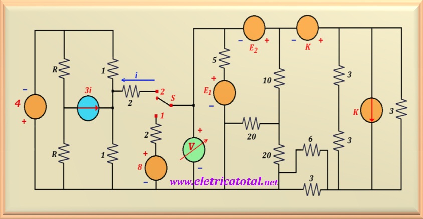
In the circuit shown in Figure 15-20.1, when the switch "S" is in position 1,
E1 = - 5 V and E2 = 5 V. Under this condition, the voltmeter
indicates 0 volts. Determine the value of the constant K, as well as the value
indicated by the voltmeter, when the switch S is in position 2 and
E1 = E2 = 5 V.
Figure 15-20.1
Solution of the Problem 15-20 -
Thévenin Method
Key in Position 1
To begin the circuit analysis, consider that the switch S is in the
position 1. Therefore, the 8 volt voltage source is included in the circuit
in series with the 2 Ω; resistor which, in turn, is in parallel with the
voltmeter. Never forget that an ideal voltmeter has an infinite resistance,
with no electric current flowing through it.
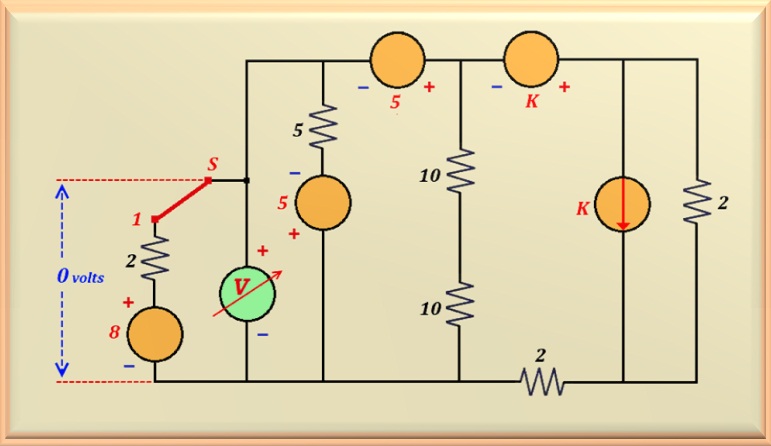
Looking closely at the circuit, several simplifications can be made.
One of them is to add the two resistors in series that are next to the current source K
resulting in an equivalent resistor with a value equal to 6 Ω. In turn, this resistor
is in parallel with the other resistor of 3 Ω which is also in parallel with
the current source K. Calculating this parallel (of 3 Ω and 6 Ω) results in a single
equivalent resistor with a value equal to 2 Ω.
Another possible simplification is to calculate the
parallel of the resistors of 3 Ω and 6 Ω (at the bottom of the circuit), which
will result in another equivalent resistor with a value equal to 2 Ω. Finally,
the parallel of the two resistors of 20 Ω can also be calculated, resulting in one of
10 Ω. In Figure 15-20.2, you can see the circuit with all the simplifications
mentioned above.
Figure 15-20.2
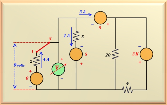
In this new configuration, we can perform two more transformations: one is to add the
two 10 Ω resistors that are in series, resulting in a single equivalent resistor of
20 Ω; the other is to transform the current source K, which is
in parallel with the 2 Ω resistor, into a voltage source in series with this
resistor.
Thus, the two resistors of 2 Ω can be added together,
resulting in a single equivalent resistor with a value of 4 Ω. Finally,
the two voltage sources, which are now in series, are added together, resulting in a single
voltage source with a value of 3 K. See Figure 15-20.3 for how the circuit looks with
these transformations applied.
Figure 15-20.3
See the currents at some points in the circuit above. According to the statement, when
switch S is in position 1, the voltmeter reading corresponds to ZERO volts.
Therefore, a current of 4 A must flow through the 8 volts source
in the direction indicated in the circuit. This is because we need to have a voltage drop
of 8 volts with polarity opposite to that of the source in the
2 Ω resistor that is in series with it. The same reasoning can be
applied to the 5 volts voltage source in series with the
5 Ω resistor. In this case, we have a current of 1 A.
Therefore, there is
3 A left to circulate through the other voltage source of 5 volts,
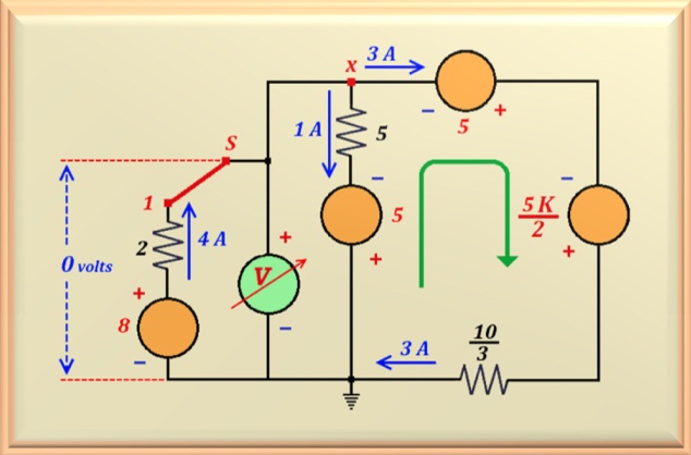
which is located at the top of the circuit. However, note that we can
perform another transformation with the resistor (of 4 Ω)
that is in series with the voltage source 3 K.
Thus, the resulting current source (= 3K/4) can
be transformed again into a voltage source in series with the resistor (10/3 Ω) that
resulted from the parallel connection between the 4 Ω and 20 Ω resistors. We present, in
Figure 15-20.4, the circuit illustrating these transformations.
Figure 15-20.4
Now, with this circuit and the values found, we can calculate the value of K.
Note that between point X and ground, we have a voltage of zero volts and
a current of 3 A flows through the right branch, as indicated by the
green arrow.
So, using the mesh equation (for voltage) in this branch, starting from point X in the direction of the
green arrow, we find:
-5 - (5/2) K + 3 x (10/3) = 0
Solving this equation, we find the value of K:
K = 2
Key in Position 2
With this information, we can remove the 8 volts source in series with the 2 Ω resistor
from the circuit, since they are not present in the circuit
when we move switch S to position 2.
Then, we can calculate the Then, we can calculate the
Thevenin equivalent of the circuit to the right of the voltmeter.
To do this, we only need to calculate the Thevenin resistance and the
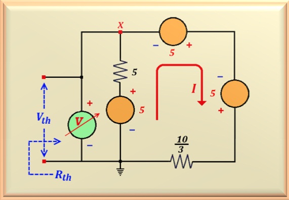
Thevenin voltage. Let's refer to the circuit shown in Figure 15-20.5.
Figure 15-20.5
To calculate the Thevenin resistance, we simply short-circuit the
voltage sources. Doing so leaves us with two resistors in parallel, namely
the 5 Ω and the 10/3 Ω. Therefore, the value is:
Rth = 2 Ω
Now, let's find the value of I, solving the mesh equation for voltage
(Kirchhoff) in the direction
indicated by the red arrow, starting from the ground point in the figure above.
- 5 + 5 I - 5 - 5 + (10/3) I = 0
Solving this equation, we find the value of I, or:
I = 9/5 A
With these values, we can calculate the value of Vth by writing the
voltage equation only for the 5 volts source and the 5 Ω resistor that are
in series. Thus:
-Vth - 5 x (9/5) + 5 = 0
Solving the equation, we find the value of Vth, or:
Vth = - 4 volts
Well, now we have the Thevenin equivalent.
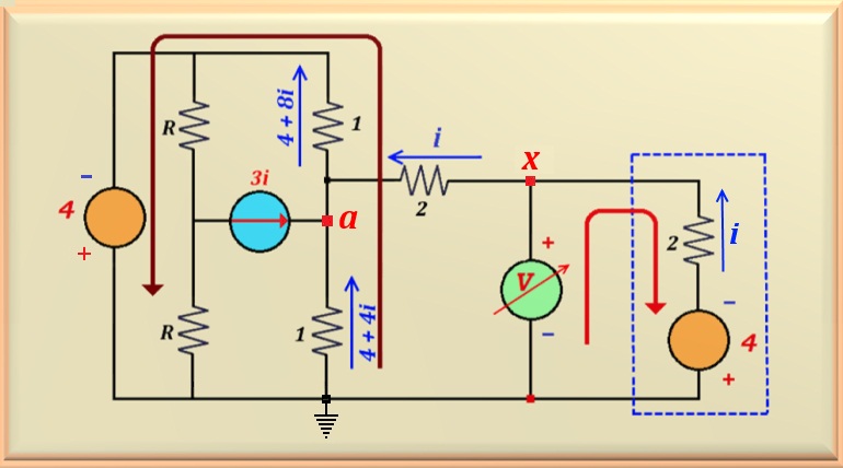
Substituting it in the original circuit, we get the circuit shown
in Figure 15-20.6, where the Thevenin equivalent is highlighted by the dashed rectangle
in blue. Note that to calculate the value measured by the voltmeter,
we must calculate the value of the electric current i.
Calculando a tensão no ponto a, podemos calcular a corrente que circula
pelo resistor de 1 ohm que interliga o ponto a à terra.
- Va - 4 i - 4 = 0
Therefore, the voltage is - Va = 4 + 4 i. That is, the voltage is
negative relative to ground. In this case, the current flows from ground to point a,
as shown in the figure below. The value
of the current is the same as Va because we divided by 1 Ω, which is the
value of the resistor.
Let's calculate the current flowing through the other resistor of 1 Ω that connects
point a to the negative pole of the 4-volt voltage source. To do this,
simply solve the equation for node a, that is:
3 i + i + 4 + 4 i = 4 + 8 i
Figure 15-20.6
Therefore, by knitting in the direction indicated by the brown arrow, which includes
the two 1 Ω resistors and the
4 volts voltage source, we can easily calculate the value of i.
4 + 4 i + 4 + 8 i - 4 = 0
By solving this equation, we can find the value of i, or:
i = - 1/3 A
So, to find the value measured by the voltmeter, let's make the mesh in the direction
indicated by the red arrow in the figure above. In other words: let's calculate the
output voltage of the Thevenin equivalent ( indicated by the blue dotted rectangle )
when a current equal to 1/3 A flows through it.
From this, we conclude that the voltage measured by the voltmeter is: