Problema 15-19 Source:
Problem 65 - List of
Electric Circuit exercises I - School of Engineering - UFRGS - 2011 -
Prof. doctor Valner Brusamarello.
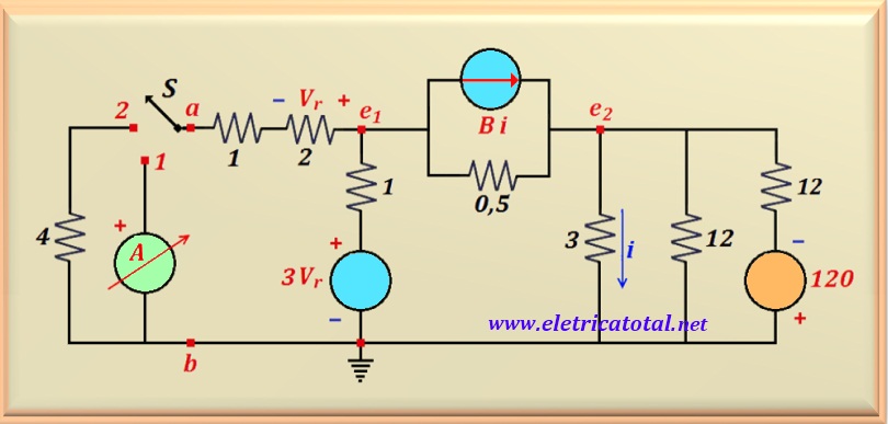
In the circuit shown in Figure 15-19.1, when switch S is in position 1, the
ammeter reads +2 A . Determine the current flowing through the 4 Ω resistor
when the switch is moved to position 2.
Figure 15-19.1
Attention:
There is a typo in the problem statement on the UFRGS problem list.
The value measured by the ammeter when the switch is in the 1 position is + 2A and not - 2A as stated on the list.
Solution of the Problem 15-19 -
Thévenin Method
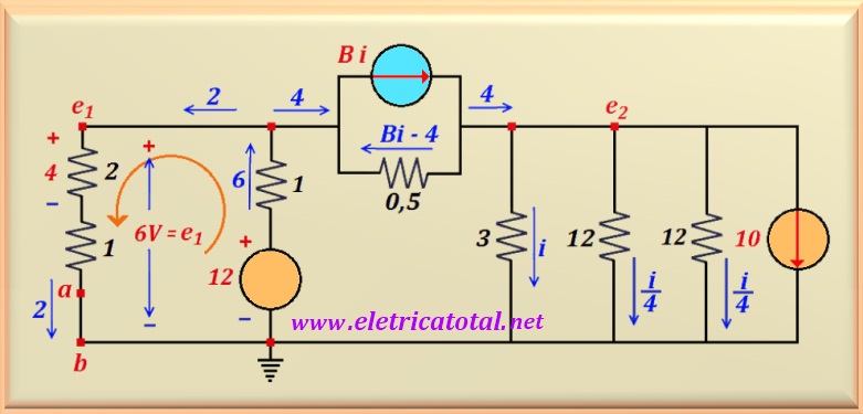
When the switch "S" is in the position 1, points a and b are interconnected by an ammeter.
It has already been studied that
an ideal ammeter has a ZERO internal resistance. Therefore, it can be stated that points a and b
are in a short circuit. This situation can be seen in Figure 15-19.2. Between
points a and b, the current measured by the ammeter flows, that is, 2 A. This current
allows us to calculate the voltage Vr. Using Ohm's law, we find 4 volts.
So, knowing Vr, the voltage-dependent source 3 Vr,
transforms into a voltage source of 12 volts, as can be seen in the figure below.
Figure 15-19.2
Note that the value of e1 is calculated using Ohm's law, that is,
e1 = 2 x 3 = 6 volts.
And to calculate the current that passes through the 1 ohm resistor and the 12 volt voltage source,
which will be called I1,
simply make the mesh equation in the counterclockwise direction as shown by the orange arrow in the figure above. And so:
-12 + 1 I1 + 6 = 0
Solving the equation, we calculate I1, or:
I1 = 6 A
Now, the value of i must be found by solving the node equation
for the point e2, or:
-4 + 10 + i + i/4 + i/4 = 0
Solving this equation, we find the value of i, or:
i = - 4 A
Since the value of i is known, it is possible to calculate e2, or:
e2 = 3 (-4) = -12 volts
Given these values, the value of B can be calculated by writing the equation:
-e1 - 0,5 ( Bi - 4) + e2 = 0
By substituting the variables with their respective numerical values and performing the calculation, we obtain:
B = 8
We need to calculate the Thévenin equivalent of the circuit seen from points a - b.
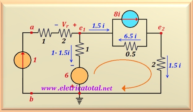
To do this, remove the ammeter and place a current source between points a - b, for example, 1 A.
We also remind you that all independent sources must be eliminated,
leaving only the dependent sources. Note that
by eliminating the 10 A current source, the three resistors that
were in parallel were replaced by a single 2 Ω resistor, through which a current of 1.5 i flows.
Furthermore, since the current source has been eliminated, an open circuit arises and therefore does not
appear in the circuit. The Figure 15-19.3 illustrates this situation.
Figure 15-19.3
The basic idea here is to find the value of Vab. This will allow us to calculate
the value of Rth. Initially, we must calculate the value of i for this new situation.
We write the loop equation for voltage (Kirchhoff's law) of the circuit indicated by the orange arrow.
6 - 1 (1 - 1.5 i) - 0.5 (6.5 i) + 2 (1.5 i) = 0
Solving the equation, the value of i is:
i = - 4 A
Knowing the value of i, it's easy to calculate Vab.
Simply draw the voltage loop (left side of the circuit) clockwise, or:
- Vab + 3 x 1 + 1 [1- 1.5 (-4)] - 6 = 0
Solving the equation, the value of Vab is:
Vab = 4 volts
Now it's easy to determine the value of Rth, because:
Rth = Vab / I = 4/1 = 4 Ω
Once the value of Rth is calculated, the switch
S is returned to the position 1. As stated earlier, the ammeter short-circuits
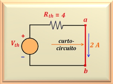
points a - b. This means that the ammeter is reading the short-circuit current (Icc = 2 A)
between points a-b. By drawing the Thévenin equivalent circuit and using this
information, the value of Vth can be calculated.
Figure 15-19.4
Notice that with the support of the circuit in Figure 15-19.4, it is easy to determine the value of
Vth, since it is enough to apply Ohm's law to the circuit.
Note that the current we call Icc = 2 A is nothing more than the
current measured by the ammeter when the switch S is in position 1. Thus:
Vth = Rth Icc = 4 x 2 = 8 volts
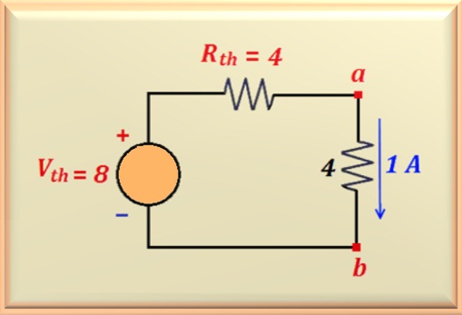
Now that the Thévenin equivalent of the entire circuit to the right of points a - b is defined,
the switch S is returned to position 2. Now, the 4 Ω resistor is inserted into terminals a - b.
Therefore, the current flowing through this resistor can be easily calculated.
Figure 15-19.5
The Figure 15-19.5 shows the final circuit with all the values found.
A very simple circuit is obtained, consisting of a voltage source powering two resistors in series.
Now, applying Ohm's law again, we calculate the current that flows through the 4 Ω resistor, or: