Problem 65-9
Source: Problem elaborated by the author of the site.
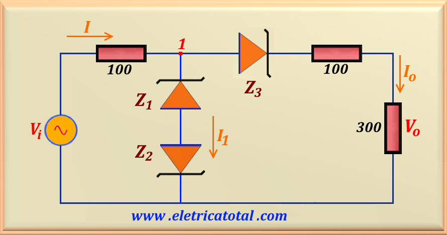
Given the circuit shown in the Figure 65-09.1, calculate the output voltage Vo, assuming that the input voltage is given by Vi = 15 sin t. Sketch a graph with the circuit transfer characteristic. Consider the voltage on the driving diode as VD = 0.7 V, VZ1 = 6.8 V, VZ2 = 4.7 V and VZ3 = 3.3 V.
Figura 65-09.1
Solution of the Problem 65-9
Note that this problem is similar to the previous one, differing by reversing Z3. Thus, when the input voltage Vi begins to grow in the positive peak direction, the three zener diodes are in the cut off zone . This is valid until the input voltage reaches the value of
Vi = 0.7 V, due to the fact that in the positive sinusoidal cycle the zener diode
Z3 acts as a common diode. In this case we have the current I = Io = 0. Therefore, we conclude that Vo = 0 in this range, or:
If 0 ≤ Vi ≤ 0.7 ⇒ Vo = 0
As soon asVi > 0.7 the zener diode Z3 go to conduction. And the output voltage, Vo, will increase as the input voltage value rises, until point 1 reaches the value of VZ1 + VD = 6.8 + 0.7 = 7.5 V. When
V1 = 7.5 V the current I1 = 0 , however
I = Io and with value equal to:
I = Io = (V1 - 0.7 ) / ( 100 + 300 ) = 17 mA
So for this value of V1 and I, the value of input voltage is:
Vi = V1 + 100 I = 7.5 + 1.7 = 9.2 V
From the circuit we see that Vo = 300 Io. Then we can write that:
Vo = 300 (Vi - 0.7 ) / 500
Therefore, for this studied voltage range we have:
If 0.7 < Vi ≤ 9.2 ⇒ Vo = 0.6 Vi - 0.42
As soon as Vi > 9.2 V, the diodes Z1 and Z2 will enter the conduction zone and therefore point 1 will have its potential fixed by the zener diodes at 7.5 V. Thus the output voltage will also be fixed at a value equal to:
Vo = 300 I = 300 x 17 (mA) = 5.1 V
Thus we can write the solution equation for this voltage range at the input.
If 9.2 < Vi ≤ 15 ⇒ Vo = 5.1 V
And for the negative cycle of the sinusoid, by the circuit we see that Z3 will behave like a zener diode, that is, when it is in the conduction zone we will have a potential difference of 3.3 V over it. Thus, while 0 ≥ Vi ≥ - 3.3 V the output voltage will be null. Therefore, we conclude that:
If 0 > Vi ≥ -3.3 ⇒ Vo = 0 V
Now we must determine at which value of V1 the zener diodes Z1 and
Z2 will enter the conduction zone. Note that for the negative sinusoid cycle, the zener Z1 diode will behave like a common diode, while the zener Z2 will act as a zener diode of VZ2 = 4.7 V. Therefore, the potential difference in
point 1 will be V1 = - ( 4.7 + 0.7 ) = - 5.4 V.
When
V1 = -5.4 V the current
I1 = 0, but
I = I o is equal to :
I = Io = (V1 + 3.3 ) / ( 100 + 300 ) = - 5.25 mA
So for this value of V1 and I, the value of input voltage is:
Vi = V1 + 100 I = - 5.4 - 0.525 = - 5.925 V
From the circuit we see that Vo = 300 Io. Then we can write that:
Vo = 300 (Vi + 3.3 ) / 500
Therefore, for this studied voltage range we have:
If - 3.3 > Vi ≥ - 5.925 ⇒ Vo = 0.6 Vi + 1.98
As soon as Vi < - 5.925 V, the diodes Z1 and
Z2 will enter conduction zone and therefore point 1 will have its potential fixed by the zener diodes at - 5.4 V. Thus the output voltage will also be fixed at a value equal to:
Vo = 300 I = 300 x ( - 5.25) (mA) = - 1.575 V
Thus we can write the solution equation for this voltage range at the input.
If - 5.925 > Vi ≥ - 15 ⇒ Vo = - 1.575 V
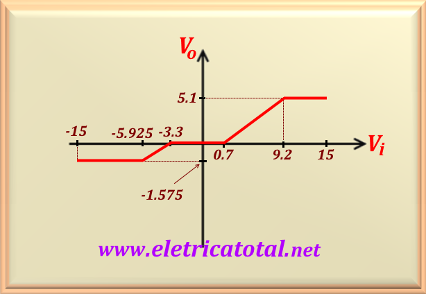
Figura 65-09.2
In Figure 65-09.2 the (non-scaled) graph with circuit transfer characteristic is shown. Note that the maximum variation in output voltage is ΔVmax = 5.1 - (- 1.575) = 6.675 volts for a variation in the input voltage of ΔVi = 15 - (- 15) = 30 volts.