Problem 65-7
Source: Problem elaborated by the author of the site.
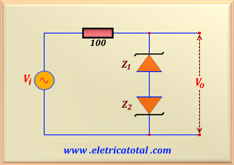
Given the circuit shown in the Figure 65-07.1, calculate the output voltage Vo , assuming that the input voltage is given by Vi = 20 sin 500 t. Sketch a graph with the circuit transfer characteristic. Consider the
voltage on the conducting diode as VD = 0.7 V, VZ1 = 6.8 V and VZ2 = 3.9 V.
Solution of the Problem 65-7
When the input voltage Vi begins to grow in the direction of the positive peak, the zener diode Z 1 will act as a zener and the zener diode Z2 will act as a common diode. In this way, for the positive cycle of the sinusoidal function, the diodes will only conduction when Vi = VZ1 + 0.7 = 6.8 + 0.7 = 7.5 V.
On the other hand, when Vi starts the negative cycle, the zener diode Z2 will act as a zener and the zener diode Z1 will act as a common diode. In this way, for the negative cycle of the sine function, the diodes will only conduction when Vi = - (VZ2 + 0.7 ) = - (3.9 + 0.7 ) = - 4.6V.
After these initial considerations we are able to determine the output voltage as a function of the input voltage. So for the positive cycle of the sinusoid we have:
And for the sinusoid negative cycle, we have:
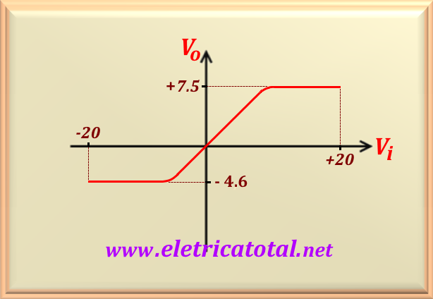
In the Figure 65-07.2 the graph with the circuit transfer characteristic is represented. Note that by
changing the slope of the line, we smooth the curve, approaching the real behavior of a zener diode.