Problem 64-5
Source:
Problem elaborated by the author's of the site.
Look at the circuit shown in Figure 64-05.1 . Assume that Vi varies randomly between 16 V and 22 V, and the load for the zener is formed by some resistors that can be activated by switches. Additionally, there is a variable load of
0 to 80 mA.
Determine the values of RS and the power dissipated by the zener and also in RS.
Figure 64-05.1
Solution of the Problem 64-5
Note that the input voltage is variable and so is the load.
Therefore, CASE 4 studied in item Theory applies.
Initially we must find the value of the minimum
load and maximum load. The minimum load occurs when the two keys,
S1 and S2 are open and the current source I1 = 0.
In that case,
we only have the 120 Ω resistor as a load. Then the minimum current is:
ILmin = VZ / 120 = 10 / 120 = 83.33 mA
Maximum load occurs when the two keys,
S1 and S2 are closed and the current source provides I1 = 80 mA. So, in that case,
the three resistors are in parallel which results in an equivalent resistor of Req = 80 Ω. Then the maximum load current is:
ILmax = (VZ / 80 ) + I1 = (10 / 80) + 0.08 = 0.205 A = 205 mA
Therefore, we can calculate the variation in current in the load, or
ΔIL = 205 - 83.33 ≈ 122 mA
Therefore, this is the current variation that the zener must absorb when we go from maximum load to minimum load.
We must add to this value the minimum current required by the zener to maintain the voltage constant at 10 V when
the load varies. Using a zener of 2 W power, the maximum current that the zener can handle is
IZmax = PZ / VZ = 2 / 10 = 200 mA
Therefore, IZmin will be:
IZmin = 10% IZmax = 10% x 200 mA = 20 mA
Note that the maximum current through the zener is
I'Zmax = ΔIL + IZmin = 122 + 20 = 142 mA
This value is lower than the maximum current supported by the zener. In principle, this zener satisfies the needs
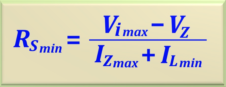
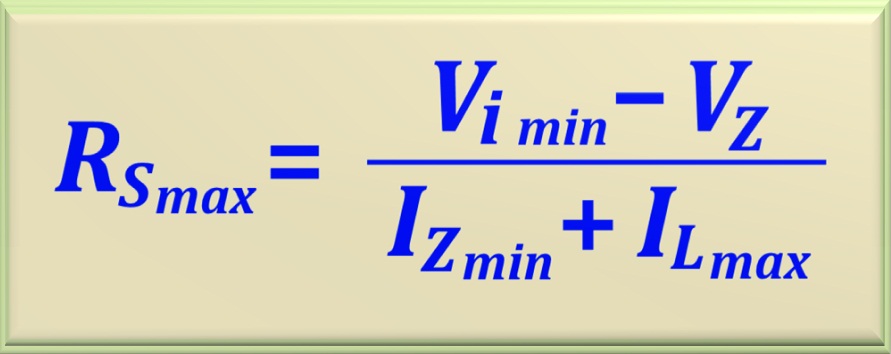
of the circuit. With these values, it is possible to calculate RSmin and RSmax using the equations eq. 64-14 and eq. 64-15, already studied. Let's repeat them here.
eq. 64-14
eq. 64-15
Remembering that in this problem, Vi(min) = 16 volts and Vi(max) = 22 volts . Soon:
RSmin = (22 - 10) / ( 0.2 + 0.08333) = 42.35 Ω
And in turn:
RSmax = (16 - 10) / (0.02 + 0.205) = 26.67 Ω
Note that RSmax < RSmin making the project unfeasible. Therefore, a zener diode with 2 W of power is not suitable for the project. Therefore, we will use a 5 W diode. Now we must recalculate the values. For
IZmax we have
IZmax = PZ / VZ = 5 / 10 = 0.5 A
Therefore, IZmin will be:
IZmin = 10% IZmax = 10% x 500 mA = 0.05 A
The other variables remain the same. Therefore, let's calculate the new values of RSmin and RSmax.
RSmax = (16 - 10) / (0.05 + 0.205) = 23.53 Ω
And in turn:
RSmin = (22 - 10) / ( 0.5 + 0.08333) = 20.57 Ω
Now, notice that RSmax > RSmin making the project viable. Therefore, a zener diode with a power of 2 W which, at first, seemed viable, turned out to be unfeasible after the calculations. Therefore, we adopted a zener with a power of 5 W, making the project viable. To find a definitive value for RS, we can calculate the
arithmetic mean between the two values found. Doing the calculations, we obtain:
RS = 22 Ω
Thus, the 5 watt zener used in the project fully meets the needs of the circuit. To find the power that the zener will dissipate, we must analyze the worst
situations for him. In this case, it will be when the input voltage is maximum, that is, Vimax = 22 V, and when the load is minimum, that is, ILmin = 0.08 A.
Thus, we can calculate the current, I''Z, over the zener by making I''Z = IRS - ILmin. Then:
Therefore, the maximum power dissipated by the zener is
PZ = VZ I''Z = 10 x 0.465 = 4.65 W
To calculate the power dissipated by the resistor RS, we must calculate the maximum current that will flow through it. Carrying out the calculation we will find the
following value: IRS = ( Vimax - VZ ) / RS = ( 22 - 10 )/ 22 = 0.545 A. Soon