Problem 32-2 Source:
Exercicie 17-3 - page 699 HAYT, William H. Jr. ,
KEMMERLY, Jack E. , DURBIN, Steven M. - Book: Análise de Circuitos em Engenharia -
Ed. McGraw Hill - 7ª Edição - 2008.
In the circuit shown in Figure 32-02.1, determine the parameters "Y".
Figure 31-02.1
Solution of the do Problem 32-2
The Y parameters are given by the following equations:
I1 = Y11 V1 + Y12 V2
I2 = Y21 V1 + Y22 V2
We calculate Y11 making V2 = 0, that is,
a short circuit in the output port. And we connected a current source I1
on the input port. Note that with the short-circuit at the output, the 20 ohms
resistor that lies between the points a - c will be in parallel with
the current source. On the other hand, the resistors of 5 and 40 ohms
will also be in parallel with each other, resulting in
40/9 ohms.
Now, this parallel is in series with the resistor of 10 ohms. This set,
which results in a value of 130/9 ohms, appears in parallel with the
resistor of 20 ohms.
Figure 31-02.2
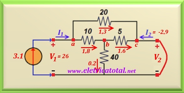
In the Figure 31-02.2, we opted for a value of I1 = 3.1 A
(only one value
convenient), in such a way that it result I2 = - 2.9 A.
Knowing the current flowing through the 20 ohms resistor
(using a current divider), which is equal to 1.3 A, we easily calculate
the value of V1 = 20 x 1.3 = 26 volts.
Therefore, we already have the necessary data to calculate the following parameters:
Y11 = I1 / V1 = 3.1 /26 = 0.119 siemens
Y21 = I2 / V1 = -2.9 /26 = - 0.112 siemens
In the same way, to calculate Y22 and Y12
we must have V1 = 0, that is, a short-circuit at the input (port 1).
We put a current source at the output (port 2) with a convenient value, for example
3.3 A.
Note that with the short-circuit at the input, the resistor of 20 ohms
between the points
a - c will be in parallel with the current source. On the other hand, the
resistors of 10
and 40 ohms will also be parallel to each other, resulting in 8 ohms.
This parallel is in series with the resistor of 5 ohms. This set results
in a 13 ohms value and appears in parallel with the resistor of 20 ohms.
Figure 31-02.3
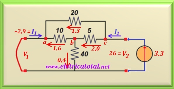
In the Figure 31-02.3, we opted for a value of I2 = 3.3 A (only one value
convenient), in such a way that it result I1 = - 2.9 A.
Knowing the current flowing through the resistor of 20 ohms
(using a current divider), which is equal to 1.3 A, we easily
calculate the value of V2 = 20 x 1.3 = 26 volts.
Therefore, we already have the necessary data to calculate the
following parameters:
Y22 = I2 / V2 = 3.3 /26 = 0.127 siemens
Y12 = I1 / V2 = - 2.9 /26 = - 0.112 siemens
As can be seen, Y12 = Y21 and with this it is concluded that the circuit is PASSIVE ou RECIPROCAL.