Problem + Hard 15-3 Source:
Problem 2 of P1 - 1st semester - 2016 -
Discipline: Electrical Circuit Engineering Analysis - ULBRA -
Prof. doctor João Carlos Vernetti dos Santos.
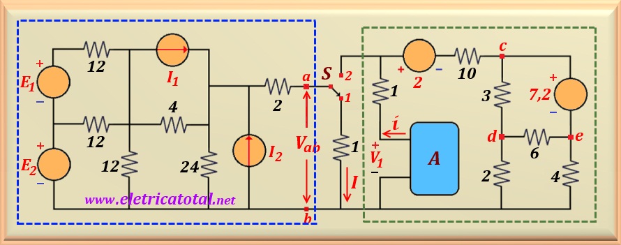
In the circuit of the Figure 15-03.1, when the switch S is in position 1,
the current I = 1.2 A. Determine the value of the voltage Vab, when the
key S is in position 2.
Figure 15-03.1
Solution of the Problem + Hard 15-3
When the key "S" is in position 1, the points a and b are
interconnected by a resistor equal to 1 ohm and through which a
electrical current of 1.2 A. This information makes it possible to calculate the
Thevenin equivalent for the circuit that is highlighted by the dashed line in blue.
To do so, eliminate the independent sources and calculate the Thevenin resistance.
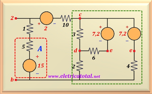
Note that when we eliminate the voltage sources E1 and E2
(they are short-circuited),
the three 12 ohms resistors are in parallel with each other. Thus, we get a single
equivalent resistance equal to 4 ohms. On the other hand, when we eliminate the current sources
I1 and I2,
they behave like an open circuit and therefore we can eliminate them from the circuit.
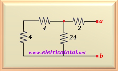
Figure 15-03.2
In the Figure 15-03.2 we can see how the simplified circuit that
will allow you to calculate the Thevenin resistance. Thus, the two 4 ohms resistors
that are in series, can be replaced by a single one with a value equal to 8 ohms.
This, in turn, will be in parallel with the 24 ohms resistor. As a result of
parallel, we obtain an equivalent resistor of 6 ohms. And finally, adding the value of this resistor with the resistor of 2 ohms which is linked to the point a, we find the value of Rth1. Let's call it this way, because we must calculate Rth2 referring to the circuit
highlighted by the dashed lines in green in Figure 15-03.1. Soon:
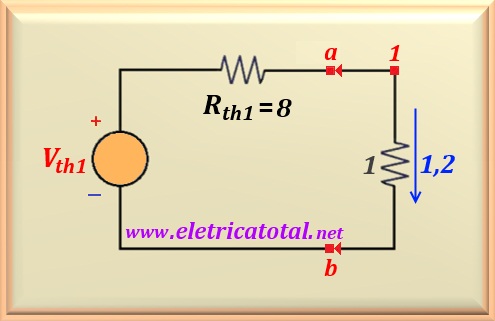
Rth1 = 8 ohms
With the value of Rth1 and considering the key S in
position 1, we can now calculate the value of Vth1. For that,
follow the circuit shown in the Figure 15-03.3.
Figure 15-03.3
We know that when we insert the 1 ohm resistor into the Thevenin equivalent, a
current of 1.2 A through the circuit. Therefore, applying Ohm's law to the circuit
we easily calculate the value of Vth1. The result will be:
Vth1 = 9 x 1.2 = 10.8 volts
Let's pay attention to the other circuit (on the right at points a-b), and calculate its
Thevenin equivalent.
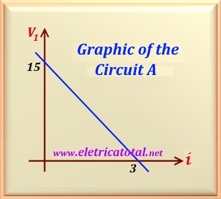
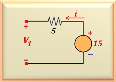
First, let's find out what the corresponding graph means
to circuit A. From the graph, we see that when i = 0 the voltage
V1 is equal to 15 volts. However, we know that when i = 0 this
represents an open circuit. On the other hand, when V1 = 0
(ie a short circuit) then the electric current takes on the value of 3 A.
Figure 15-03.4
Notice the circuit shown in the Figure 15-03.4. When the circuit behaves
as an open circuit, we have i = 0 and therefore V1 = 15 V.
However, if we apply a short circuit to its output (V1 = 0 V),
for a current to flow i = 3 A, we must have a resistor in
series with a voltage source equal to
R = 15/3 = 5 ohms.
Thus, the circuit shown above satisfies the conditions required by the graph.
In this way, we can redraw the circuit highlighted with a dashed line in green,
and replace the "box" that represents circuit A, shown in dashed red,
as shown in the Figure 15-03.5.
Figure 15-03.5
In the figure to the side we see the redrawn circuit. Note that in addition to introducing the circuit
from "box A", we made a explosion voltage source of 7.2 volts
(Right side of circuit).
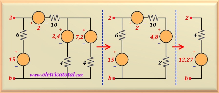
Now it is easy to see that we can transform the entire circuit that is highlighted
by the green dashed line, across a single voltage source in series with a resistor. Follow along in Figure 15-03.6
below, the transformations made in the circuit.
Figure 15-03.6
Note that the circuit shown on the right in the figure above is exactly the same.
Thevenin equivalent of the circuit we are analyzing. Note that Rth2 = 4 Ω and
Vth2 = 12.27 V. We could have
used another method to find the result. However, note that doing
font transformations quickly we get to the final result.
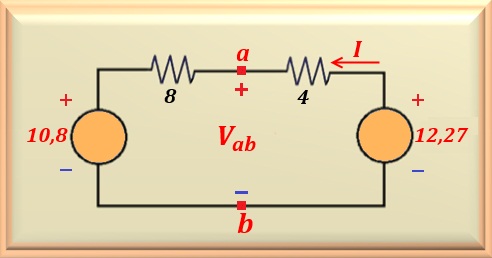
As we have the two Thevenin equivalents it only remains to connect them
and calculate the value of Vab. See how it looks in the Figure 15-03.7
the final circuit.
Figure 15-03.7
Note how the circuit in the figure on the right made it easy to determine the value of
Vab, as it is enough to apply Ohm's law to the circuit.
Note that this case is when the key S is in position 2.
Therefore, we can calculate the current I.
I = (12.27 - 10.8) / 12 = 0.1225 A
With the value of the current flowing through the circuit, we can calculate the voltage
Vab, or:
Vab = 10.8 + 8 x 0.1225 = 11.78 volts
For this calculation we use the circuit to the left of the points ab. We would arrive at the same result using the circuit on the right of points a - b.