Problem + Hard 15-2 Source:
Problem 38 - List of Problems
Electrical Circuits I of the School of Engineering - UFRGS - 2011 - Prof. doctor Valner Brusamarello.
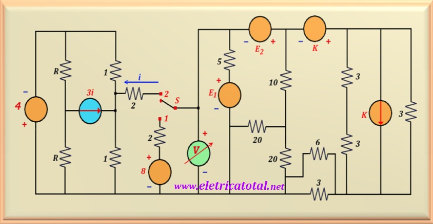
In the circuit of Figure 15-02.1, when the switch "S" is in position 1,
E1 = - 5 V and E2 = 5 V. In this condition the voltmeter
indicates 0 volts. Determine the value of the constant K, as well as the value
indicated by the voltmeter when the switch S is in position 2 and
E1 = E2 = 5 V.
Figure 15-02.1
Solution of the Problem + Hard 15-2
Key in Position 1
To begin the analysis of the circuit, consider that the switch S is in the
position 1. In this way, the voltage source of 8 volts is included in the circuit
in series with the 2 ohm resistor which, in turn, is in parallel with the
voltmeter. Never forget that an ideal voltmeter has infinite resistance,
no electrical current flowing through it.
Looking closely at the circuit, there are conditions to perform several simplifications.
One of them is to add the two resistors in series that are located next to the current source K,
resulting in a resistor value equal to 6 ohms. This resistor, in turn,
is in parallel with the other 3 ohms resistor which is also in parallel with
the current source K. Calculating this parallel (of 3 and 6 ohms) results in a single
resistor value equal to 2 ohms. Another possible simplification is to calculate the
parallel of the 3 and 6 ohms resistors (at the bottom of the circuit), where
will result in one more resistor equal to 2 ohms. Lastly, also
it is possible to calculate the parallel of the two resistors of 20 ohms, resulting in one of
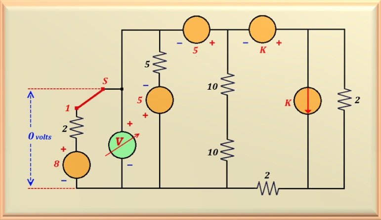
10 ohms. In the Figure 15-02.2, you can see the circuit with all the simplifications
mentioned above.
Figure 15-02.2
In this new configuration, we can carry out two more transformations: one is to add the
two 10 ohms resistors that are in series, resulting in a single resistor of
20 ohms; another is to transform the current source K, which is
in parallel with 2 ohms resistor, across a voltage source in series with this
resistance. In this way, the two resistances of 2 ohms can be added and,
as a result, a single resistor of value equal to 4 ohms is obtained. And finally,
add the two voltage sources, which are now in series, resulting in a single
voltage source of value 3 K . See in the Figure 15-02.3 how the circuit with
these transformations performed.
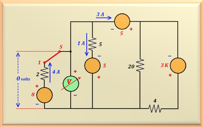
Figure 15-02.3
See in the circuit that we indicate the currents in some points of the circuit. This
based on the information given in the problem statement which states that when the
switch S is in position 1, voltmeter indicates zero volts.
Therefore, in the source of 8 volts a current of 4 A must circulate,
in the direction indicated on the circuit. This is due to the fact that we need to have a drop
voltage of 8 volts, with opposite polarity to the source, in the resistor
of 2 ohms that is in series with it. The same reasoning can be
applied to the voltage source of 5 volts in series with the resistor of
5 ohms. In this case, we have a current of 1 A. Soon, left
3 A to circulate through the other voltage source of 5 volts,
located at the top of the circuit. However, notice that we can
carry out one more transformation with the resistor (from 4 ohms)
which is in series with the voltage source 3 K.
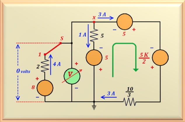
Thus, the resulting current source (= 3K/4) can
be transformed, again, into a voltage source in series with the resistor (10/3) that
resulted from the parallel between the 4 and 20 ohms resistors. We present, in
Figure 15-02.4, the circuit with all these transformations.
Figure 15-02.4
Now, with this circuit and the values found we can calculate the value of K.
Notice that between point X and ground, we have a voltage of zero volts and
a current of 3 A flows through the right branch, as indicated by the
green arrow.
So, doing the mesh equation (for voltage) in this branch, starting from the point X in the direction
from the green arrow, we find:
-5 - (5/2) K + 3 x (10/3) = 0
Solving this equation, we find for the value of K:
K = 2
Key in Position 2
With this information in hand, we can remove the 8 volts source from the circuit
in series with the 2 ohms resistor, as they are not included in the circuit
when we move the key S to position 2. So, one can calculate the
Thevenin equivalent of the circuit to the right of the voltmeter.
For this, we only need to calculate the Thevenin resistance and the
Thevenin voltage. Let's refer to the circuit that appears in the Figure 15-02.5.
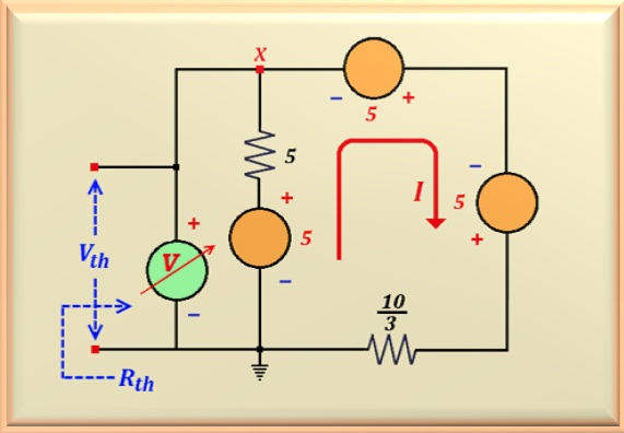
Figure 15-02.5
To calculate the Thevenin resistance just short-circuit the
voltage sources. Doing this, we are left with two resistors in parallel
(the 5 and the 10/3 ohms). So the value is:
Rth = 2 Ω
Now let's find the value of I by doing the mesh equation for voltage
(Kirchhoff) in the sense
indicated by the red arrow, starting from the ground point in the figure above.
- 5 + 5 I - 5 - 5 + (10/3) I = 0
Solving this equation, one finds the value of I, or:
I = 9/5 A
With these values in hand, the value of Vth can be calculated by writing the
voltage equation just for the 5 volts source and the 5 ohms resistor that
are in series.
Like this:
-Vth - 5 x (9/5) + 5 = 0
Solving the equation finds the value of Vth, or:
Vth = - 4 volts
Well, now we have the Thevenin equivalent.
Substituting in the original circuit, we are left with the circuit shown
in the fFigure 15-02.6, where the Thevenin equivalent is highlighted by the rectangle
dashed in blue. Note that, to calculate the value measured by the voltmeter,
we must calculate the value of the electric current i.
By calculating the voltage at point a we can calculate the current flowing
by the 1 ohm resistor that connects point a to ground.
- Va - 4 i - 4 = 0
Therefore, the voltage is - Va = 4 + 4 i. That is, the voltage is
negative with respect to earth. In this case the current flows from ground to point a,
as shown in the Figure 15-02.6. The value
of the current is the same as Va because we divide by 1, which is the
resistor value.
Let's calculate the current flowing through the other 1 ohm resistor, which interconnects
the point a to the negative pole of the voltage source of 4 volts. For this
just make the equation of the node a, that is:
3 i + i + 4 + 4 i = 4 + 8 i
Figure 15-02.6
Therefore, meshing in the direction indicated by the brown arrow, which includes
the two 1 ohm resistors and the source
voltage of 4 volts, we can easily calculate the value of i.
4 + 4 i + 4 + 8 i - 4 = 0
Solving this equation we can find the value of i, which is equal to:
i = -1/3 A
So to find the value measured by the voltmeter, let's mesh in the direction
indicated by the red arrow in the figure above. In other words, let's calculate the
output voltage of the Thevenin equivalent (indicated by the rectangle
dashed in blue) when a current equal to 1/3 A flows through it.
Hence, it is concluded that the measured voltage is: