Problem 55-10
Source: Problem 13 - List of RLC Problems - Discipline
Electrical Circuits of the School of Engineering - UFRGS - 2017 - Prof. Dr. Valner Brusamarello.
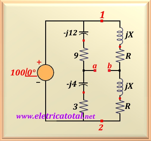
Determine Vab in module and phase according to the circuit
shown in the Figure 55-10.1.
Solution of the Problem 54-10
Note that it is possible to calculate the impedance of the 1-to-2 branch by adding the values of the components, as they are connected in series.
Therefore, the impedance will be:
Thus, knowing the impedance we can calculate the value of I1, or:
Performing the calculation:
Note that the impedance between the point 1 and the point a is Z1a = 9 - j12 = 15∠-53.13°. In this way, we can calculate the voltage between the point 1 and the point
a, or:
On the 1-b-2 branch, note that the impedance between points 1-b and b-2 are exactly the same
regardless of the values of R and X<. This implies that
V1b = Vb2. And since the source voltage is V = 100∠0°, it is concluded that:
To find the value of Vab just make the upper mesh, or:
Performing the numerical substitution and calculating:
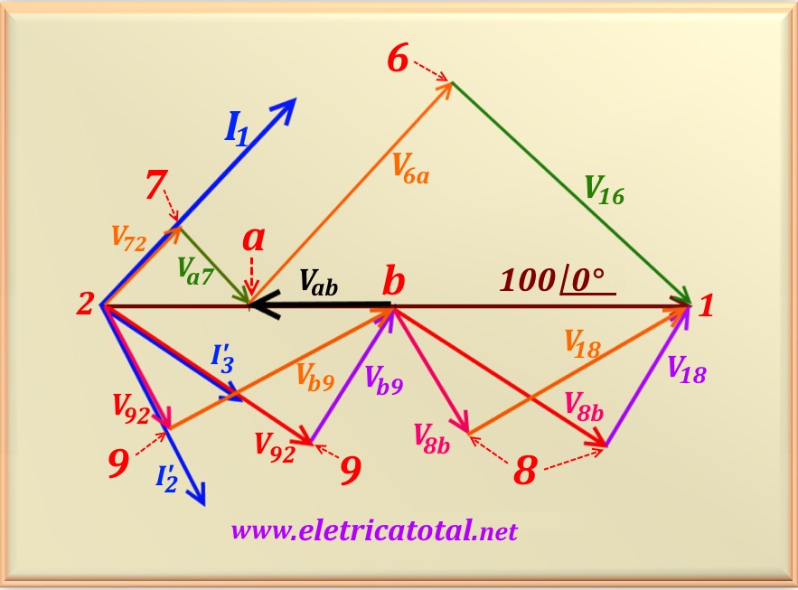
In the Figure 55-10.2, we present a phasor diagram of the voltages and currents in the circuit. Notice that the phasors that are above the reference voltage correspond to the branch containing capacitors. Analyzing the branch that is between the points 2 and a: note that the voltage V72
is in phase with current I1 and is the voltage on the 3 ohm resistor; the voltage
Va7 is the voltage on the capacitor -j3 and is delayed by 90° in relation to the voltage on the resistor, V72; the phasor sum of these two voltages is the voltage
Va2.
Now let's look at the branch that is between the points a and 1: the voltage V6a is the voltage across the 9 ohms resistor and is in phase with I1 as can be seen in the diagram; the voltage V16 is the voltage across the capacitor and is delayed by
90° in relation to the voltage across the resistor, V6a; the phasor sum of these two voltages is the voltage V1a, whose value has been calculated and is equal to V1a = 75∠0°.
Now let's make an analysis of the part that is below the reference voltage and, in this case, analyzing the branch containing the inductors.
To be clear that the solution of the problem is independent of the values of R and XL, we chose to represent two currents, I'2 and I'3, with different phase angles, which means two different values for R and XL. Note that in the case of
I'3, results V92 > Vb9, then R > XL. And to
I'2, results V92 < Vb9, then R < XL. It is then verified that, for any values of R and XL the same solution is obtained for
Vab.
See, in the diagram, Vab pointing in direction contrary the voltage of the power supply.
This justifies the value found Vab = -25∠0° = 25 ∠180° V.


