Problem 46-1
Source: Problem elaborated by the author of the site.
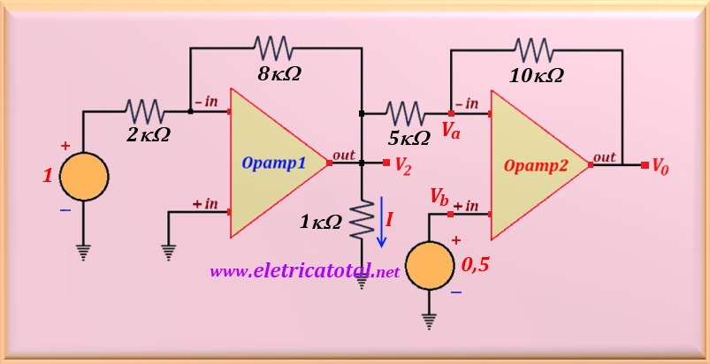
For the circuit shown in the Figure 46-01.1, calculate Vo and the current I.
Solution of the Problem 46-1
Notice that Opamp1 is in the inverter configuration. Therefore, easily
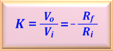
we can calculate the gain of the circuit to the closed loop using the equation below.
From the circuit Ri = 2 kΩ and Rf = 8 kΩ.
Substituting these values into the above equation, we have:
Calculating the value of V2, or:
In possession of the value of V2 the value of I can be calculated. Like this:
To calculate the value of Vo, we write the equations for the a node of
Opamp 2. Then:
For an operational amplifier ideal , is valid the relation already studied where
Va = Vb = 0.5 V. Rearranging the
equation for Vo we obtain the following relation:
Performing the numerical substitution and calculating Vo, we obtain:
Notice the fact that, Opamp2 operates in an inverting configuration for the output voltage
V2, while for the source of 0.5 volts, it operates in a configuration
non-inverting. For this reason the output voltage V2 é amplificado por um fator
2, while the 0.5 volt source is amplified by a factor 3.


