In the previous chapter we have seen a general overview of the operational amplifier.
In this chapter, we will see that depending on the topology used, the configuration acquires its own name.
Let's look at the topology called inverter configuration.
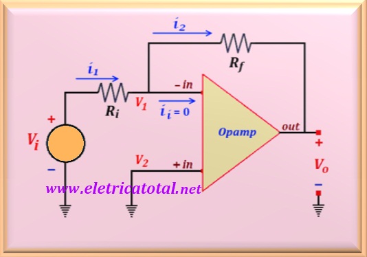
In this configuration the non-inverting input is grounded and the input signal, represented by the voltage source Vi, is connected to the inverter input
through the resistor Ri. Between the output and the inverting input we have
the feedback resistor, here represented by Rf.
In the Figure 42-01, we see a typical inverter circuit. Let us calculate the voltage gain to the closed loop of this amplifier, which is nothing more than the relation between
Vo e Vi.
As indicated in the circuit, ii = 0, then
i1 = i2. And from there we can write:
But as we saw in chapter 41, we know that V1 = V2. In the case above, we can write:
Substituting these values into the equation above and working algebraically, we arrive
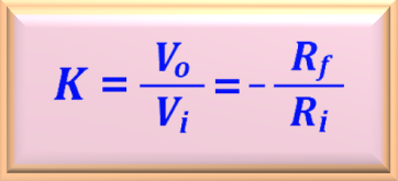
the final equation, or:
Notice the negative signal in the equation. This means that the input signal, in addition to being amplified, appears at the inverted output, that is, by 180 degrees in relation to the input signal. More than that: the voltage gain of the circuit only depends on the two external resistors, being totally independent of the type of operating amplifier used.
It should be noted that in addition to this circuit is an amplifier (|K| > 0)
when Rf > Ri, it can also behave as an attenuator (|K| < 0), just do
Rf < Ri.


