Problem 97-7
Source: Adapted from example 2-60 - page 192 -
SAHDEV, S. K. - Book: Electrical Machines - 1st edition - Cambridge University Press - 2018.
A 500 kVA transformer "A" is connected in parallel with a 150 kVA transformer "B". In this configuration, a 750 kVA load is connected with PF = 0.8 lagging.
Their open-circuit voltages are 405 V and 415 V, respectively. Transformer "A"
has 1% resistance and 5% reactance, and transformer "B" has 1.5% resistance and
4% reactance. Find:
a) The current circulating through the transformer secondaries when they operate without load.
b) The apparent power that each transformer supplies to the load.
Solution of the Problem 97-7
In this type of problem, it is more advantageous to work with the impedances in their ohmic values. The problem statement does not provide the value of the voltage across the load. Therefore, we will adopt a value of VL = 400 V.
This will not imply an appreciable error. So, initially, we will calculate the values of RA and
XA, values of the transformer "A". First, we must calculate the value of IA.
Applying the basic concepts of power, we have:
IA = SA / VL = 500,000 / 400 = 1,250 A
The value of RA is defined as:
RA = %RA x VL / IA
Replacing the variables with their respective numerical values and performing the calculation, we obtain:
RA = (1 / 100) x 400 / 1,250 = 0.0032 Ω
Using the same reasoning, we can calculate the value of XA.
XA = %XA x VL / IA
Replacing the variables with their respective numerical values and performing the calculation, we obtain:
XA = (5 / 100) x 400 / 1,250 = 0.016 Ω
Now, let's apply the same procedure to transformer "B". Thus, we will calculate the value of
IB :
IB = SB / VL = 150,000 / 400 = 375 A
Following the procedure, we have:
RB = %RB x VL / IB
Replacing the variables with their respective numerical values and performing the calculation, we obtain:
RB = (1.5 / 100) x 400 / 375 = 0.016 Ω
Using the same reasoning, we can calculate the value ofXB.
XB = %XB x VL / IB
Replacing the variables with their respective numerical values and performing the calculation, we obtain:
XB = (4 / 100) x 400 / 375 = 0.0427 Ω
At this point, it is possible to write the impedances of the two transformers.
ZA = 0.0032 + j 0.016 = 0.0163 ∠ 78.5° Ω
ZB = 0.016 + j 0.0427 = 0.0456 ∠ 69.46° Ω
And the phasor sum of the two impedances is:
ZA + ZB = 0.0032 + j 0.016 + 0.016 + j 0.0427
Performing the calculation, we obtain:
ZA + ZB = 0.0192 + j 0.0587 = 0.0618 ∠ 71.88° Ω
Item a
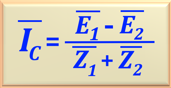
Using the values found above, we can calculate the current that flows through the transformer secondaries when they operate
without load, using eq. 97-09, repeated below.
eq. 97-09
Replacing the variables with their respective numerical values and performing the calculation, we obtain:
IC = (405 - 415 ) / 0.0618 ∠ 71.88° = - 161.8 ∠ -71.88° A
Item b
Initially, we must find the value of the load impedance, that is, ZL. Since we know the power of the load
and the voltage across it, we can calculate its value by applying the following equation:
SL = VL2 / ZL
Making a small algebraic arrangement and replacing the variables with their respective numerical values, we find:
ZL = 4002 / 750 ∠ - 36.87°
Performing the calculation, we obtain:
ZL = 0.214 ∠ 36.87° = 0.171 + j 0.128 Ω
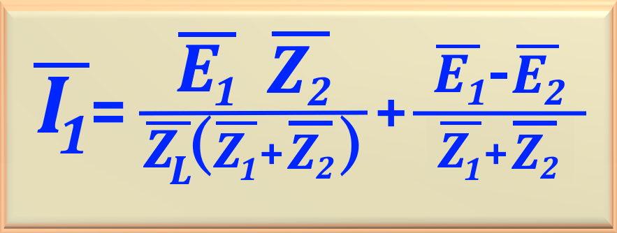
Now, we can calculate the actual power contribution of each transformer when the load is connected to the system.
First, let's calculate the value of IA. To do this, we will use eq. 97-10, repeated below.
eq. 97-10
Replacing the variables with their respective numerical values, we have:
IA = 16.705 ∠ 73.41° / 0.0138 ∠ 110.72°
Performing the calculation, we obtain:
IA = 1,210.51 ∠ -37.31°
Therefore, the power supplied to the system by transformer "A" is:
SA = VL x IA = 400 x 1,210.51 ∠ -37.31°
Performing the calculation, we obtain:
SA = 385,120 - j 293,489 = 484,204 ∠ -37.31° VA
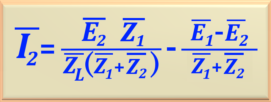
To calculate the value of IB we will use eq. 97-11, repeated below.
eq. 97-11
Replacing the variables with their respective numerical values, we have:
IB = 8.4843 ∠ 68.85° / 0.0138 ∠ 110.72°
Performing the calculation, we obtain:
IB = 614.80 ∠ -41.87°
Therefore, the power supplied to the system by transformer "B" is: