To begin our study of transformers, let's define what an ideal transformer is.
Ideal Transformer - is the transformer where there is no accumulated energy in the magnetic field (losses in iron is zero),
there is no inductance, the wire has no resistance (losses in copper is zero) and the coupling coefficient between coils is unitary.
In the ideal transformer the input power is equal to output power.
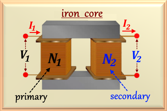
The winding where we apply the voltage source we call PRIMARY and the winding where we connect the load we call SECONDARY.
We usually represent the number of turns of the primary by N1 and the number of secondary turns by
N2, as can be seen in Figure 91-01, where we represent a transformer in its didactic format.
Figure 91-01
Note that in the construction of the transformer there is no direct contact between the primary and the secondary.
They are completely independent circuits. There must also be no electrical contact between the wires that make up the windings
and the iron core. They must be isolated from each other. For the transformer to work, we must apply a sinusoidal or cosine voltage
to the primary, V1, (attention: transformers do not work with direct current, or DC) and this voltage
will generate a variable flux in iron core. This variable flux, which runs through the entire iron core, will induce a voltage,
V2, in the secondary winding (Faraday's lawSee here!). Knowing the value of V1,
the voltage V2 in the secondary depends only on the so-called ratio of transformation given by
the ratio between the number of turns that make up the primary and secondary, according to eq. 91-01, below.
So if N1 > N2 we say that the transformer is a
voltage reducer. Otherwise, that is, if we have N1 < N2, then we say that the
transformer is an elevator of voltage.
In the Figure 91-02 we present the schematic of a transformer.
Figure 91-02
Where the variables are:
V1 - Electrical voltage applied to transformer primary
V2 - Electrical voltage removed from the transformer secondary
I1 - Electrical current in transformer primary
I2 - Electrical current in transformer secondary
N1 - Number of turns of transformer primary
N2 - Number of turns of transformer secundary
ZL - Load connected to secondary
P1 - Power delivered to transformer primary
P2 - Power delivered to the load
An important parameter of the transformer is the so-called transformation relation, which is defined as the
relation between N1 and N2 and represented by the letter a, given by:
eq. 91-01
On the other hand, there is a direct relation between transformer voltages and transformation ratio,
given by:
eq. 91-02
And as said before, the input and output powers in the ideal transformer are equal, that is
P1 = P2 = V1 I1 = V2 I2.
So this lets you write that:
eq. 91-03
These mathematical relationships are of fundamental importance for understanding the operation of a transformer.
In the study of transformers we can work with the so-called impedance reflection. That is, we can reflect the
impedance from primary to secondary and vice versa. It depends on the convenience of one or the other. Let's look at how
these reflections are made.
The secondary impedance can be calculated as the ratio of secondary voltage and current. Referring to the circuit above, we can write that:
Zs = V2 / I2 = ZL
But by eq. 91-03 we know that V1 = a V2 and
I1 = I2 / a. Thus, calculating the impedance that the circuit offers to the primary, we find:
Zp = V1 / I1 = a V2 / (I2 / a) = a2 ZL
That is, when we reflect the secondary to primary impedance, we must multiply the secondary impedance by the square of the transform relationship. In short:
Just as we reflect the impedance from secondary to primary, we can reflect that from primary to secondary.
From eq. 91-03 we concluded that I2 = a I1 and also V2 = V1 / a. So by calculating the impedance that the
circuit offers to the secondary, we find:
We conclude that when we reflect the primary to secondary impedance, we must
divide the primary impedance by the square of the transform relation, a.
In short:
Paying attention to Figure 91-01, we notice that the transformer windings are seated on a core
of ferro-silicon. This is due to the fact that ferrosilicon has a high magnetic permeability and creates a strong
magnetic flux through the core that surrounds the two windings (primary and secondary) of the transformer. With this, we obtain
a strong interaction between the two windings and we can consider a unitary coupling coefficient between them. In that case,
we can use Faraday's Law, as we studied in chapter 75
(see here!) and we can rewrite the eq. 75-13, as follows:
eq. 91-06
We know that in an ideal transformer the winding resistances are equal to zero. In this case, we can say that the
induced voltage is equal to the voltage applied to the winding, that is, E1 = V1. Normally a
Transformer is powered by a sinusoidal voltage. Then we can define V1 = Vmax sin (ω t).
Based on the definitions above and doing algebraic work on eq. 91-06 we can write eq. 91-07.
eq. 91-07
As our interest is to calculate the magnetic flux,Φ, from eq. 91-07 we easily find
the flow value by integrating this equation and obtaining:
eq. 91-08
Another way to write the magnetic flux is through eq. 91-09, where we use the fact that
- cos x = sin (x - 90°). Then:
eq. 91-09
Where Φm represents the maximum magnetic flux and can be expressed by
eq. 91-10. It should be noted that the magnetic flux, according to eq. 91-09, is 90° late
in relation to the applied voltage. This becomes clearer when looking at Figure 91-03, below.
eq. 91-10
In eq. 91-10 we use the well-known relation ω = 2 πf. Note that the magnetic flux is
directly proportional to the applied voltage and inversely proportional to the frequency. Normally we aim to maintain
constant flux peak to fully utilize the magnetic circuit. This means that changes in voltage or
frequency must be made so that the relationship between voltage and frequency
be maintained. Thus, if we double the applied voltage, then to keep the flux constant we must double the frequency
of tension. This is what Figure 91-03 shows.
Figura 91-03
Often, in problems, we know the value of the flux and want the value of the induced voltage. For that,
just work algebraically the eq. 91-10, obtaining:
eq. 91-11
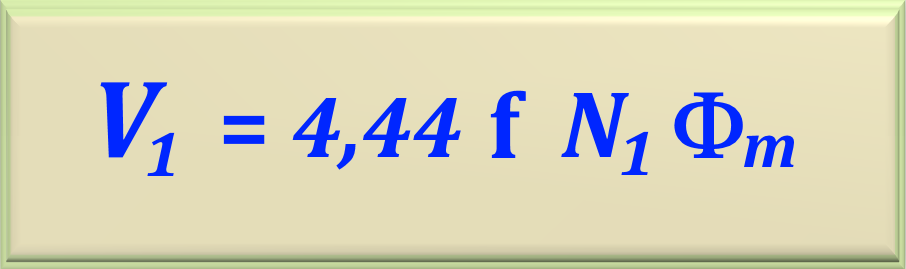
In transformer design, it is usual to use the induced voltage at its rms value and not at its
maximum or peak. As we learned in chapter 52, to transform maximum voltage to effective voltage,
just divide the maximum voltage value by √2. See here!
Then the effective value of V1 is given by eq.91-12.
eq. 91-12
In a similar way we can find the effective value of V2, given by eq.91-13.