We define autotransformer as a transformer in which the winding is common to both the primary and secondary.
In a comventional transformer, the primary and secondary are isolated from each other. This is not the case in the autotransformer,
where the two windings are not electrically isolated from each other, and part of the winding acts as the primary while the rest
of the winding acts as the secondary. Thus, an important characteristic of the autotransformer is its ability to increase
or decrease voltage.
In an autotransformer, the primary winding (where the power enters) can be either the high voltage side or the low voltage side,
depending on whether it operates as a step-down or step-up transformer.
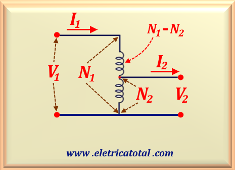
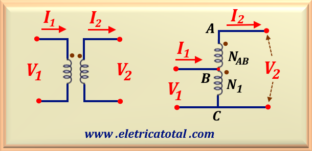
Suppose that in the circuit shown in Figure 94-01, a sinusoidal voltage V1 is applied to the
AC winding. In this case, an exciting current begins to flow through the AC winding. Ignoring the voltage
drop across the internal impedance of the transformer, we can determine the voltage per turn in the AC
winding as follows: we use the relation V1 / N1, and therefore in the BC winding
it will be (V1 / N1) N2.
Figura 94-01
Now, suppose a load is connected between points r and s. In this case, the current I2
will flow through the load. Assuming that the losses in the autotransformer are negligible, we can write:
Potência de Entrada = Potência de Saída ⇒ P1 = P2
Naturally, under these conditions, eq. 91-02 and eq. 91-03 are valid, repeated below for greater clarity and understanding.
(studied in chapter 91, See here!).
eq. 91-02
eq. 91-03
Note that these equations are identical for conventional transformers with two independent windings.
In the case of autotransformers, it is interesting to define a new variable to simplify the equations.
Therefore, we define the variable k, according to eq. 94-01.
eq. 94-01
Let us assume, at a given instant, an excitation current flows from point A to point C,
establishing a magnetomotive force (MMF) in the core in the vertical upward direction. Then, the current in the winding BC
must flow from point C to point B to create an MMF opposite to that created by the excitation current,
as determined by Lenz's law
( Lenz's law - See here!).
We know that the magnetomotive force (MMF) must remain constant to maintain the magnetic flux in the core.
When a load is connected to the secondary of the transformer, a current I2
flows in the secondary winding. To neutralize the effect of this current and keep the MMF constant, the primary
winding must absorb an additional current I1 from the power supply. This additional current I₁ is
necessary to counterbalance the MMF produced by the current I2 in the secondary.
In this way, the magnetic flux in the transformer core remains constant, ensuring the proper functioning of the autotransformer.
We must be aware that, in the AC winding, the current I1 flows from point A to point C,
while in the BC winding, the current I2 flows from point C to point B.
In this case, the current I2 is greater than the current I1, since V2 < V1.
Therefore, at each instant, the MMF's generated by the currents oppose each other. So, we can write that:
ICB = I2 - I1
eq. 94-02
Thus, the MMF generated by the winding AB is given by:
FAB = I1 ( N1 - N2 ) = I1 N1 - I1 N2
However, remember that we are considering negligible losses in the autotransformer. Therefore, we have that
I1 N1 = I2 N2.
Thus, the above equation can be written as:
FAB = I2 N2 - I1 N2
= N2 ( I2 - I1 )
But, using eq. 94-02, we can write:
FAB = N2 ( I2 - I1 ) =
N2 IBC = FBC
Therefore, it is evident that all transforming action (electromagnetic induction) occurs between the windings of
section AB and section BC. In other words, the volt-amperes through the winding
AB are transferred by means of transforming action to the load that is connected to the winding of section
BC, that is, at the terminals designated r-s and shown in Figure 94-01.
From what was presented in the previous item, we can define transformed power, which we will represent by STR,
as that which uses electromagnetic induction as a transforming action, transferring electrical energy from one winding to another.
Thus, we can write:
STR = VAB IAB = I1 ( V1 - V2 )
eq. 94-02a
The total power that will be consumed from the power source and used by the primary in the transformation
will be called input power and symbolized by Sin. Thus, we can write
Sin = V1 I1. Therefore, we can calculate what portion of the input power
is transferred inductively. To do this, let's determine the ratio between the two powers:
Using eq. 91-03 (shown above) and eq. 94-01, we can write:
STR / Sin = 1 - ( 1 / a ) = 1 - k
eq. 94-03
Thus, we conclude that the portion of the input power (Sin = V1 I1)
transferred to the output by inductive action is given by STR = ( V1 - V2 ) I1.
Therefore, the extra portion consumed by the load at the output is due to direct conduction, since there is an electrical
connection between the primary and secondary. Thus, representing direct conduction by Scon, we have:
In an autotransformer, part of the power is transferred directly between the primary and secondary, without passing
through the windings. This allows it to operate with an apparent power higher than the nominal power of the windings.
In other words, it can be more efficient and more economical in certain applications, especially when the voltage
difference between the primary and secondary is not very large. To better understand this idea, let us take
Figure 94-02 as a reference.
Figura 94-02
In this item, we will represent the apparent power by the letter S. Thus, for the apparent power of input, we can write:
S1 = V1 I1
And for the apparent power of output, we have:
S2 = V2 I2
The apparent power is present in the autotransformer windings, that is, the power resulting from electromagnetic induction and is determined by:
STR = ( V2 - V1 ) I2
So, using the relation STR = V1 ( I1 - I2 )
and relating it to the other equations already developed, we can, after some algebraic manipulation, find the
ratio between the apparent input power (or output, since they are the same) and the apparent power that
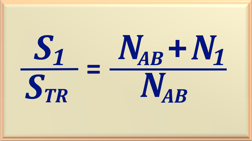
effectively flows through the autotransformer windings. Therefore:
eq. 94-07
Therefore, eq. 94-07 describes the nominal apparent power advantage of the autotransformer
over the conventional transformer. Note that the smaller the NAB winding, the
greater the advantage. This is in agreement with what was mentioned at the beginning of this item, where we stated that
it would be more advantageous when the voltage difference between the primary and secondary was not too large.
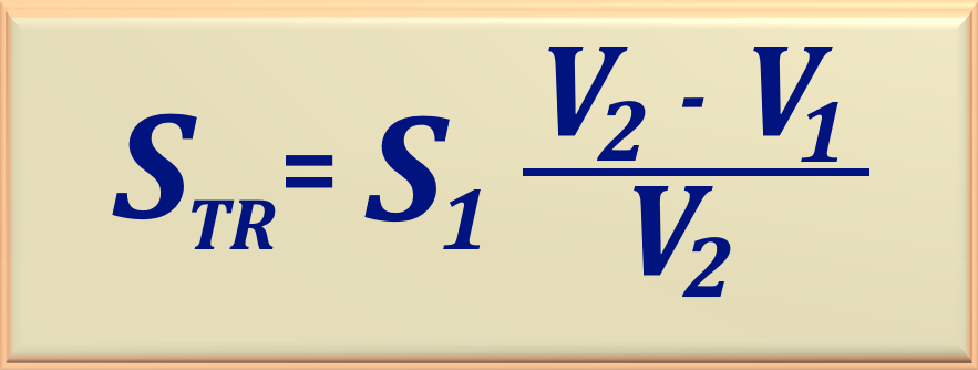
Another way to express eq. 94-07 is using the voltages involved in the primary and secondary,
according to eq. 94-08.
eq. 94-08
Take as an example a 5,000 kVA autotransformer that connects a 110 kV system to a 138 kV
system. Using eq. 94-08, we can calculate the nominal apparent power in the
windings of this autotransformer.
STR = 5.000 ( 138 - 110 ) / 138 = 1.015 kVA
The autotransformer would have a nominal rating of only 1,015 kVA for the windings, whereas a
conventional transformer would have a nominal rating of 5,000 kVA to do the same job. The autotransformer
could have a volume up to 5 times smaller than the conventional transformer and would also be much lower
in cost, due to the reduced use of copper and iron. For this reason, it is highly advantageous to install autotransformers
to connect voltages of similar values.
It is very important to note that it is usually not possible to simply modify the connections of a common transformer
so that it operates as an autotransformer. The reason is that if a common transformer is connected as an autotransformer,
the insulation on the low voltage side of the transformer may not be robust enough to withstand the full output voltage.
In transformers built especially as autotransformers, the insulation of the smaller coil
is as robust as that of the larger coil.
We know that the length of copper required in a winding is directly proportional to the number of turns, and the cross-sectional
area of the wire used in the winding is related to the rated current. Thus, the weight of copper required in a conventional
transformer with two independent windings is proportional to the total power of the transformer.
N1 I1 + N2 I2
No caso de um autotransformador, o peso de cobre necessário é proporcional a:
I1 ( N1 - N2 ) + ( I2 - I1 ) N2
To find the relationship between the weight of copper required in an autotransformer and in a conventional transformer,
which we will call kw, we do:
By manipulating this equation algebraically and remembering that N1 I1 = N2 I2,
we will find:
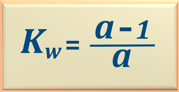
kw = 1 - ( N2 / N1 ) = 1 - ( 1 / a)
Rearranging the terms, we find eq. 94-10:
eq. 94-10
The eq. 94-10 demonstrates that, for example, in an autotransformer with a primary to secondary voltage
ratio of 100:33, when applying eq. 94-10, the result obtained is 0.67. This indicates that
when using an autotransformer, only 67% of the copper is required compared to what would be required
if we were using a conventional transformer with two independent windings. Therefore, the reduction in copper
usage is 100% - 67% = 33%.
On the other hand, by naming the copper savings as Kcu, it can be calculated directly by eq. 94-11 below.
eq. 94-11
To better understand, let's analyze an example.
Example 94-1
The primary and secondary voltages across an autotransformer are 230 V and 75 V, respectively.
Calculate the current in all windings when the load current is 200 A.
Also calculate the copper savings.
Resposta
To calculate the currents we will use eq. 91-03a, shown below.
eq. 91-03a
So, applying the equation, we have:
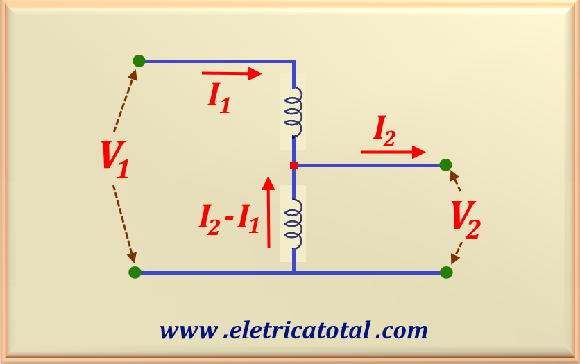
I1 = I2 ( V2 / V1 ) = 200 ( 75 / 230 ) = 65,2 A
And the current flowing through the common winding is given by I2 - I1, that is:
I2 - I1 = 200 - 65,2 = 134,8 A
See Figure 94-07, in which we represent the autotransformer and its currents and voltages.
Figura 94-07
As for the copper economy, let's use eq. 94-10. Then, the value of kw,
knowing that a = 230 / 75 = 3.066, is:
kw = ( 3,066 - 1 ) / 3,066 = 0,674
Since the autotransformer uses 67.4% of copper compared to the conventional transformer, the copper savings are: