Problem 91-1
Source: Problem developed by the site author.
Be an ideal transformer powered by a 220 V source and having 1000 turns in the primary.
What must be the number of turns in the secondary so that we have a voltage of 110 V in it?
Solution of the problem:
click here!
Problem 91-2
Source: Problem developed by the site author.
If in the previous problem a 100 ohm load was connected to the secondary, what would be the currents in the primary and secondary? What would be the power dissipated in the load? Compare this result with the power supplied by the network to the transformer.
Solution of the problem:
click here!
Problem 91-3
Source:
Problem developed by the site
author.
Be an ideal single-phase transformer powered by voltage ratings 13200/660 volts .
On the secondary a load is connected whose value is ZL = 10 + j6 ohms.
a) Calculate the current at the secondary and primary of the transformer.
b) Calculate the real and reactive power the load consumes.
c) Calculate the module of the impedance that is seen by the network.
Solution of the problem:
click here!
Problem 91-4
Source:
Adapted from example 2-1 - page 73 -
CHAPMAN, Stephen J. - Book: Fundamentals of Electric Machines - 5th Edition - Ed. McGrawHill - 2013.
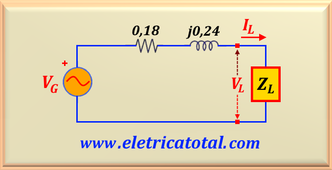
A single-phase power system consists of a generator with voltage VG = 480∠0° V that supplies a
value load ZL = 4 + j3 Ω through a transmission line that has an impedance
Zline = 0.18 + j0.24 Ω, as shown in Figure 91-04.1.
It is asked:
a) Determine the voltage VL on the load.
b) Calculate the real and reactive power that the load consumes.
c) Calculate the losses in the transmission line.
Solution of the problem:
click here!
Problem 91-5
Source:
Adapted from example 2-1 - page 73 -
CHAPMAN, Stephen J. - Book: Fundamentals of Electric Machines - 5th Edition - Ed. McGrawHill - 2013.
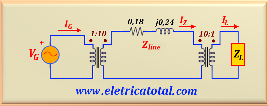
A single-phase power system consists of a generator with voltage VG = 480∠0° V that supplies an ideal transformer whose transformation ratio is 1:10. This transformer is connected to another transformer
ideal with a transform ratio of 10:1 across a transmission line that has an impedance
Zline = 0.18 + j0.24 Ω. The secondary of the second transformer is connected to a load of
value ZL = 4 + j3 Ω, as shown in Figure 91-05.1.
It is asked:
a) Calculate the currents in the circuit as shown in Figure 91-05.1.
b) Calculate the real and reactive power that the load consumes.
c) Calculate the losses in the transmission line.
Solution of the problem:
click here!


