Problem 44-2
Source: Problem elaborated by the author of the site.
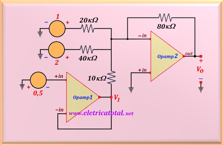
Calculate the voltage V1 and Vo in the circuit shown in the Figure 44-02.1.
Solution of the Problem 44-2
Clearly, Opamp1 is connected in the buffer configuration. In the theoretical part regarding
buffer, it was studied that this device faithfully copies the input voltage to the output.
Therefore, the voltage at the buffer output is the voltage at the input, that is, V1 = - 0.5 volts.
Opamp2 is connected in the adder configuration and the output voltage will be: