Problema 22-6
Source:
Adapted from question 1 of the 2nd Electrical Circuits I exam. - UFRGS - 2023.
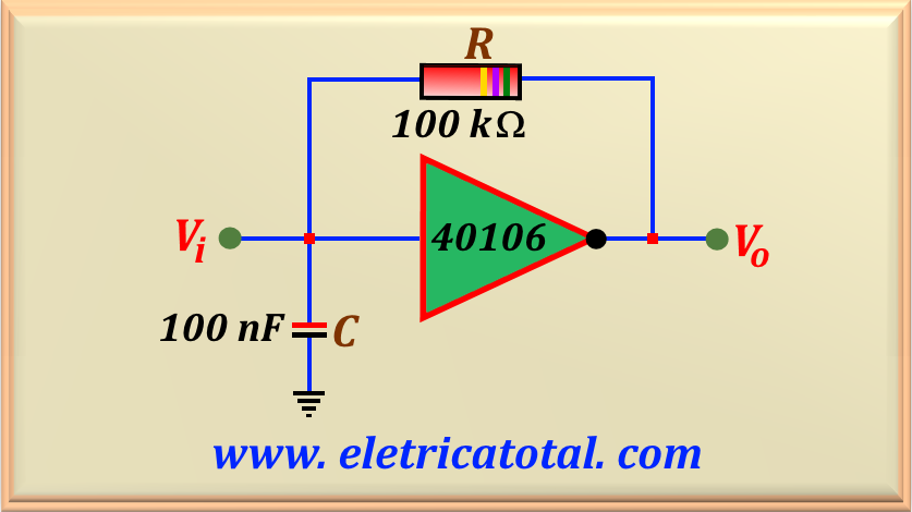
The circuit shown in Figure 22-06.1 presents an RC circuit coupled to a CMOS inverter. When the
input voltage (relative to ground)
at the inverter input is less than or equal to 1.9 V, its output shows a voltage of 5 V. And when the voltage at its input
is greater than or equal to 2.9 V,
its output is at 0 V. If the input is between 1.9 V and 2.9 V, the output remains unchanged.
Assume that the capacitor is initially discharged and that the current entering the inverter input port is zero.
a) Find the equations for the circuit response:
b) Sketch a diagram of the voltage across the capacitor and at the CMOS output:
c) Determine the maximum and minimum values across the capacitor:
d) Find the frequency generated by the circuit.
Figure 22-06.1
Solution of the Problem 22-6
Item a
Since the capacitor is initially discharged, the input voltage is zero, and consequently, we have 5 V at the inverter output.
Because the output is connected to the capacitor by the resistor, the capacitor will begin to charge until it reaches a
voltage of 2.9 V. When the voltage across the capacitor,
that is, the inverter input, reaches the value of 2.9 V, the inverter output switches to a voltage equal to 0 V. At this point,
the capacitor begins to discharge through the resistor until it reaches a voltage of 1.9 V.
When the voltage across the capacitor (or the inverter input) reaches this value, the inverter output switches to a voltage of 5 V.
And this cycle repeats as long as the circuit is powered by a power source.
First, let's calculate the time constant of the circuit.
τ = R C = 105 x 10-7 = 10-2 s = 10 ms
We will use the equation eq. 22-03. Therefore, we must determine Vi and Vf.
Vi = 0 V Vf = 5 V
Substituting these values into eq. 22-03 we obtain the desired equation.
VC (t) = 5 ( 1 - e- 100 t ) V
eq. 22-6.1
From the instant t = 0, the capacitor begins the charging cycle through the resistor. Since we know that the
inverter switches when the voltage at its input is equal to
2.9 V, we will find the instant when this happens, using eq. 22-6.1. Therefore:
2.9 = 5 ( 1 - e- 100 t ) V
Solving this equation, we can easily find the value of the instant. Let's call it t1, or:
t1 = 0.008675 s = 8.675 ms
Now we must determine the new equation that will describe the capacitor's discharge through the resistor. We know that:
Vi = 2.9 V Vf = 0 V
Therefore, substituting these values into eq. 22-03 we obtain the desired equation, or:
VC (t) = 2.9 e- 100 (t - 8.675 ms) V
eq. 22-6.2
Starting at time t1, the inverter switches to a voltage of 0 V at its output
and the capacitor begins a discharge cycle until it reaches a voltage of 1.9 V.
Let's determine this instant, which we will call t2, using the eq. 22-6.2.
1.9 = 2.9 e- 100 (t - 8.675 ms)
Solving the equation, we find:
t2 = 0.01291 s = 12.91 ms
At t2, when the inverter input reaches 1.9 V, the inverter output
switches to a voltage of 5 V and restarts the capacitor charging cycle.
And the equation governing the capacitor charging from t2 is given by:
VC (t) = 5 - 3.1 e- 100 (t - 12.91 ms) V
eq. 22-6.3
To find eq. 22-6.3, we use eq. 22-03 with the values below:
Vi = 1.9 V Vf = 5 V
Finally, let's determine the time t3 when the capacitor (or the inverter input voltage)
reaches a voltage of 2.9 V. Substituting this value into eq. 22-6.3, we find:
t3 = 0.0168 s = 16.80 ms
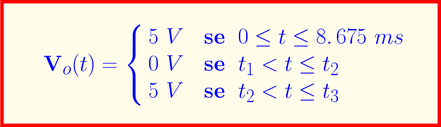
Therefore, we can describe the output voltage as:
Item b
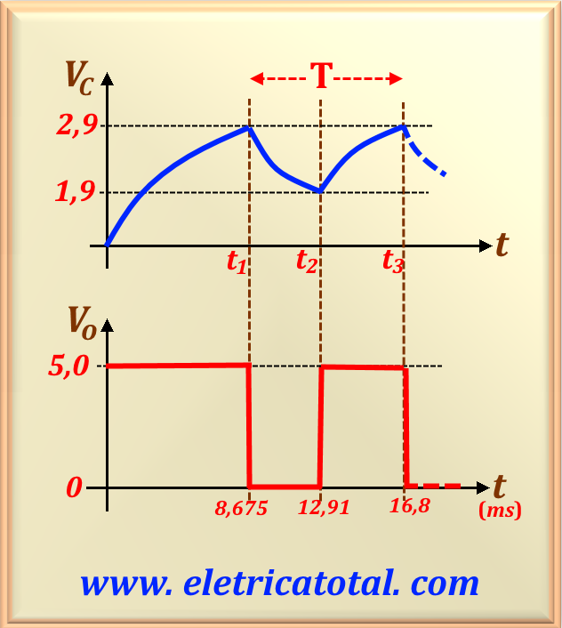
As requested by the problem, the sketch of the voltage graph across the capacitor and at the inverter output is shown in Figure 22-06.2.
Figure 22-06.2
Item c
From the graph shown in item b, we can easily determine the maximum and minimum voltage values across the capacitor, that is:
Vmin = 1.9 V Vmax = 2.9 V
Item d
To calculate the frequency of the generated signal, we will disregard the first charge of the capacitor.
Thus, we will consider the system in steady state.
Note that, from the graph shown in item b, we can calculate the time when the output voltage
is 0 V and then 5 V. Therefore, we have:
t0 = t2 - t1 = 0.004235 s = 4.235 ms
t5 = t3 - t2 = 0.00389 s = 3.89 ms
Note that, since we have different charging and discharging times for the capacitor, the square wave at the CMOS output is asymmetrical.
Therefore, we can determine the period of the generated signal by adding the two times above. So:
T = t0 + t5 = 0.008125 s = 8.125 ms
And as we know, frequency is the inverse of the period. Therefore: