Problem 10-7 Source:
Problem elaborated by the author of the site.
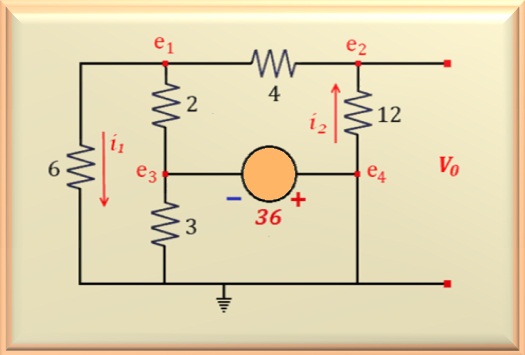
On the circuit show in Figure 10-07.1, determine:
a) The currents i1 and i2.
b) The voltage Vo.
Solution of the Problem 10-7
See in the figure above that the e4 point was connected close
to earth (due to the short circuit) and thus the voltage source assumes the
configuration shown in the figure. Note that the resistor of 3 ohms is in
parallel with the voltage source.
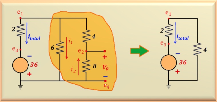
Therefore, it can be eliminated from the circuit. And also, as the resistor of
6 ohms is connected to the e1 point, you can redraw the
circuit
for clarity. The Figure 10-07.2 illustrates the redesigned circuit.
Notice in the figure above that the circuit highlighted in yellow is an association
of resistors
and we can simplify it. The 4 and 8 ohms resistors are in series
resulting in an equivalent resistance of 12 ohms. However, this equivalent
resistance is in parallel with the resistor of 6 ohms. Then, it turns out
that all circuit highlighted in yellow can be replaced by a single resistor with a
value equal to 4 ohms, which is the equivalent resistance of the parallel
between the resistors of 6 and 12 ohms. With this, to the right
of the figure we see the final result. This circuit will allow computing
itotal. Therefore,
just use the Ohm's law. Adding the two resistors we find the value of
6 ohms. Soon:
Notice that itotal was drawn in the same direction as the positive pole of the source voltage, obeying the conventional sense of the electric current. Therefore, its value is positive.
In the left circuit, e1 will have a negative value and its calculation is possible by doing the mesh equation:
With the value of e1 we can calculate the value of i1
e i2. To do this simply apply the Ohm's law, or:
Note that i1 has negative value because e1
is also negative. This means that its direction is opposite to that indicated in the circuit.


