Problem 74-1
Source: Problem developed by the author of the site.
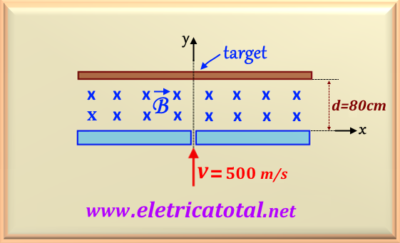
A positively charged particle, as shown in Figure 74-01.1, with mass equal to
m = 5 x 10⁻⁷ Kg and charge equal to q = 10 -4 C, when it
passes through a hole in a bulkhead, it enters an environment that
it is under the action of a magnetic induction field of B = 2.5 T. Next to the bulkhead,
there is a target 80 cm from the bulkhead. If, when passing through the hole, the particle has
a velocity of v = 500 m/s, determine:
a) What lateral distance from the orifice will the particle collide with the target?
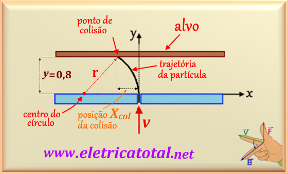
b) The particle's trajectory (show through a diagram).
Solution of the Problem 74-1
As was studied in the theoretical part, item 2.1, when a particle with an electric charge
penetrates a magnetic induction field, it undergoes a lateral force and, as a consequence,
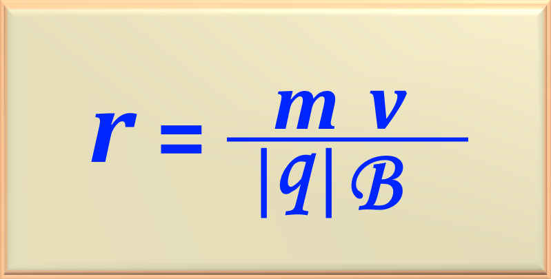
it starts to perform a circular motion. To determine the radius of the circle, we must use
eq. 74-05 . For greater clarity we will reproduce the eq. 74-05, below:
Substituting the numerical values given by the statement of the problem, we have
Performing the calculation we find the radius of the circle, or
We must determine whether the particle's path is going to deviate to the left or right.
Using the right hand rule (see hand position in Figure 74-01.2) we can easily see
that the particle will shift to the left. Note that we have established a reference x-y .
Since the path is a circle, and the radius of the circle is r = 1 m , using the equation of the circle
we will be able to determine the x position of the collision, as we already know that the
y position collision occurs at y = 0.8 m. So:
Performing the calculation, we find
Now, pay attention to the fact that the value found for x is in reference to the center
of the circle. But the statement of the problem calls for the distance of the collision with
reference to the orifice of the bulkhead. Therefore, this distance will be:
Therefore, we can state that in the x-y referential the collision with the target will happen in
(-0.4 m; 0.8 m) . See the diagram requested on Figura 74-01.2.


