Problem 47-4
Source: Problem 5.87 - page 187 -
ALEXANDER, Charles K., SADIKU, Matthew N. O. - Book:
Fundamentos de Circuitos Elétricos - 5ª Edição - Ed. McGraw Hill - 2013.
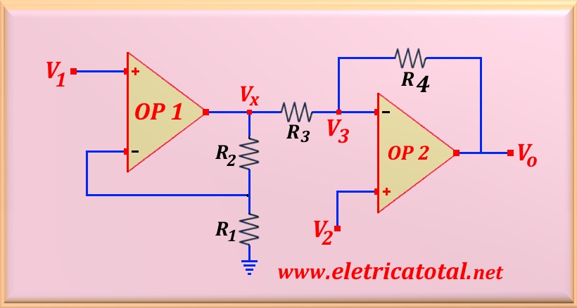
The circuit shown in the Figura 47-04.1 represents an instrumentation amplifier with two operational amplifiers. Deduct an expression for Vo
in terms of V1 and V2. Explain how this
amplifier can be used as a subtractor.
Solution of the Problem 47-4
This circuit is composed of an operational amplifier ( OP 1) connected in
the non-inverting configuration and another ( OP 2) in the
configuration inverter. Whereas the current flowing through the R4 is the same that
circulates through R3, we can write:
Of the circuit, virtually, V2 = V3 and thus rearranging the terms:
On the other hand, the following relation is obtained from OP 1:
Substituting this value into the previous equation finds the desired relation.
For this circuit to act as a subtractor, it is sufficient to do R4 = R1
and also R3 = R2. Thus, the end result is a subtractor circuit with gain equal to
K = 1 + ( R4 / R3). Then, Vo will be given by:


