Problem + Hard 11-2 Source:
Problem 51 - List of
Electric Circuit exercises I - School of Engineering - UFRGS - 2011 -
Prof. doctor Valner Brusamarello.
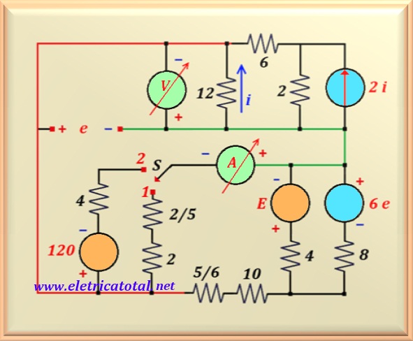
In the circuit of the Figure 11-02.1, when the switch "S" is in "position 1" the voltmeter
indicates - 15 Volts.
a) Determine the value of "E".
b) Determine the ammeter reading when the switch "S" is in "position 2".
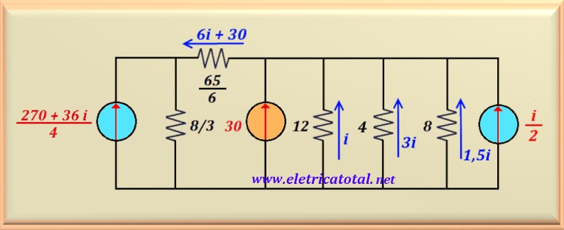
Figure 11-02.1
Solution of the Problem + Hard 11-2 -
Transf. of Sources
Item a
In the Figure 11-02.1, we emphasize through the green and red lines the points that meet
interconnected. The circuit has been redrawn for a more understandable view. Note that the resistors that were in series
were added and their values appear in the circuit. By the data of the problem we have that V = -15 volts,
and as e = - V, it follows that e = 15 Volts.
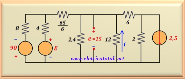
Thus, replacing the font 6.e by its numerical value or, 90 Volts.
From the circuit, the value of i can be calculated.
i = V / 12 = - 15 / 12 = - 1.25 A
As the value of i is negative, meaning that the current flows in the opposite direction to that indicated in the figure, then the source of current of 2. i = 2.5 A, must have its direction reversed.
The resistor of value 65/6 Ω that appears in the circuit, is the equivalent resistance
of the series of resistors of 10 and 5/6. Try to understand the changes that have been
carried out and conclude that the two circuits are absolutely identical, although with
different topologies, as can be seen in the Figure 11-02.2.
Figure 11-02.2
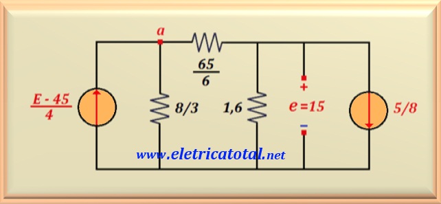
It is possible to transform sources in the three sources of the circuit and
put your numerical values. See, in the Figure 11-02.3, that the two fonts on the left were
transformed into a single current source in parallel with a resistor of 8/3 ohms,
which is the parallel value of the 4 and 8 ohms resistors that were in series with the sources
of tension. On the other hand, in the current source of 2.5 A we made a Thevenin
and after, a Norton, resulting
a current source of 5/8 A in parallel with a resistor of 1.6 ohms, this resistor being the result of the
parallel between the 12 , 8 and 2.4 ohms resistors.
Figure 11-02.3
As we know the value of e = 15 volts, then we can calculate the current
flowing through the 1.6 ohms resistor. Adding this value with the source of 5/8 A
we find the current flowing through the 65/6 ohms resistor. Carrying out the calculation we find the value of 10 A.
Thus, adding e with the voltage drop across the resistor of
65/6 ohms we find the voltage at point a, which is:
Va = ( 65/6 ) 10 + 15 = 123.33 volts
Knowing the value of Va, we can calculate the current that
passes through the 8/3 ohms resistor, finding:
i8/3 = 123.33 / (8/3) = 46.25 A
Therefore, the current that the source must supply is the sum of this current plus the 10 amperes
that passes through the 65/6 ohms resistor, that is:
( E - 45 ) / 4 = 46.25 + 10 = 56.25 A
Portanto, basta fazer o cálculo e encontramos o valor de E, ou:
E = 270 volts
Item b
If we move the switch S to position 2, we remove from the circuit the
resistor of 2.4 ohms and in its place we put a voltage source of
120 Volts in series with a 4 ohms resistor, as we can see in the
Figure 11-02.4.
Figure 11-02.4
It should be noted that the value measured by the voltmeter when the switch S was
in position 1, it is not valid when we pass the S key to position 2.
So, from the circuit, we see that e = - 12 i. Therefore, at the voltage source 6.e,
we replace its value by 72.i with reversed polarity, because e is negative,
meaning that the polarity of the voltage source must be reversed. The voltage source E,
we replace it with its value found in the previous item, 270 volts. Understood these
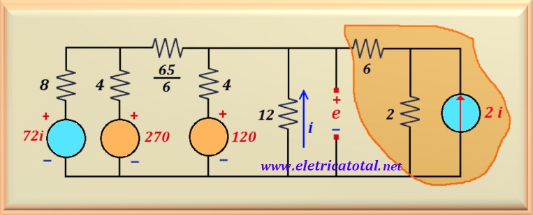
substitutions, we will transform the three voltage sources in series with resistors. Let's get current sources in
parallel with resistors. We will also do a transformation on the highlighted circuit
in yellow. See in the Figure 11-02.5 how the circuit was transformed.
Figure 11-02.5
Note that adding all the currents on the right side of the 65/6 ohms resistor,
we obtain the current flowing through this resistor, totaling 6 i + 30 ampere. Now,
if we make a transformation on the left current source and the 8/3 ohms resistor,
we can calculate the value of i. Remember that about the side components
right of the circuit we have the voltage e = - 12 i.
See in the Figure 11-02.6, that we represent these components by the voltage - e.
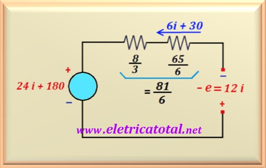
Figure 11-02.6
To make the mesh and calculate the value of i, we just need to know the potential difference
of the circuit on the right. Therefore, we replace it with the value of the voltage as a function of i. Now,
just set up the equation. Starting from the positive pole of - e, counterclockwise, we get:
12 i + (81/6) (6i) + (81/6) 30 + 24 i + 180 = 0
Carrying out the calculation, the value of i is found, or:
i = - 5 A
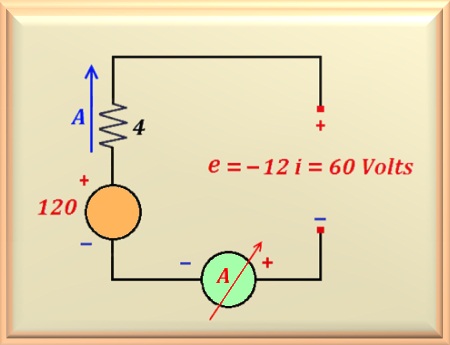
With this value and using the circuit of the Figure 11-02.7, we are able to calculate the measured current
by the ammeter. This current crosses the 4 ohms resistor, which is in series
with a voltage source of 120 Volts.
Figure 11-02.7
From the circuit, we calculate A by doing the mesh equation in the sense
clockwise and starting from the negative pole of the voltage source, or:
- 120 + 4. A + 60 = 0
Of course, we do not take into account the internal resistance of the ammeter, since we know that
for an ideal instrument its internal resistance is equal to ZERO. Therefore,
solving the above equation, we find the value measured by the ammeter, or: