Another very powerful method in solving electrical circuits is the Nodal method , also called, in some technical literatures,
the Nodal Tension method. Basically, the method consists of analyzing the currents that arrive and leave a node. For this, we designate
a voltage for each node in the circuit.
In the Figure 12-01 we see a circuit that has four nodes, one of which is the earth. The voltage at nodes a
and b are known (with respect to earth). However, we do not know the voltage in the node c. Using the convention
that currents arriving at nodes are considered
negative and currents leaving the nodes are considered positive, we can write equations for each node in function of
these currents.
We must remember that the algebraic sum of the currents competing for a node must be equal to ZERO. Analyze the equation
eq. 12-01 that we write for the node c.
Let's look at it from right to left. Notice that the first portion, Vc / 20, is nothing more than the current from node c to the earth, because we consider the earth to have voltage NULL.
The second portion represents the current leaving the node c
to the node a, because the electric voltage at node a is 60 volts. So by subtracting the voltage at the node c by the voltage at the node a, we have the potential difference over the resistor of 10 ohms that is interconnecting nodes a and c. Now, dividing this voltage by the resistor value, we find the value of the electric current that flows through the same.
Similarly, the third portion represents the current from the node c towards the node b, since the electric voltage in the node b is 30 volts.
The subtraction of the two voltages is the potential difference over the resistor of 10 ohms that is interconnecting nodes c and b. Thus, by dividing this potential difference by the
resistor of 10 ohms, we find the value of the electric current that flows through it.
Notice that the above equation tells us that the algebraic sum of all currents competing for node c must be equal to ZERO. In other words, each portion of the equation represents a current of the branches that form the node c. So, solving the system, because we only have the Vc as incognita, we find:
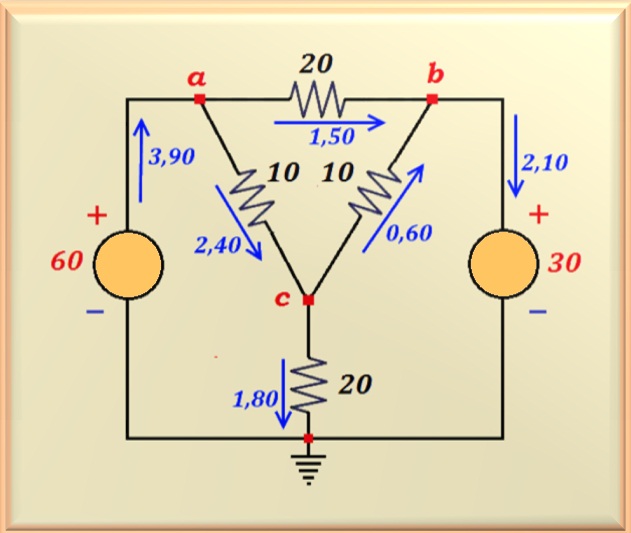
Therefore, we are now knowing the electrical voltages at all nodes. Thus, it is very easy to determine the currents throughout the circuit. We present in the Figure 12-02 the circuit with the currents in all the components.
Note that to determine the currents, we must apply the law of Ohm to each resistor, since we know the potential difference over each one of them. In order to determine the currents that circulate through the voltage sources, we use the fact that the algebraic sum of currents competing for nodes a and b must be equal to ZERO (KLC, Kirchhoff's law for currents).
As an exercise the student can make a balance of power of the circuit and check the validity of the
results.


