Problem 11-10 Source:
Problem 68 - List of Electrical Circuit Exercises I -
School of Engineering - UFRGS - 2011 - Prof. Dr. Valner Brusamarello.
In the circuit show in Figure 11-10.1, determine the value read by the ammeter
A when the S key is in position 2, knowing that when the
S key is in position 1 the circuit contained and highlighted by the
orange rectangle in the figure, transfers the maximum possible power.
Figure 11-10.1
Attention -
There is a typing error in the list response. The correct value
of the ammeter reading is 3 A and not 9 A, as it appears in the list.
Problem solving using Thévenin-Norton Methodclick here!
Solution of the Problem 11-10 -
Method of Transforming Sources
First we must remember that a circuit like the one highlighted in an orange rectangle in the figure above can transfer the maximum power to the load (in this case, load = 6 ohms) if the load value is
equal to the internal resistance of the circuit.
From the graph shown to the right of the figure, we realize that the value of the voltage source of the circuit A is 126 volts. It is not possible to know the value of the internal resistance (which is in series with the voltage source). But based on what has been said above, we can calculate, since the parallel of this with the resistance of 9 ohms must be equal to 6 ohms for there to be the maximum power transfer . Therefore, we can write:
9 Rin / (9 + Rin) = 6
Performing the calculation we find:
Rin = 18 ohms
With this value we can find the Thévenin equivalent of the whole circuit that is inside
of the orange rectangle. The Thévenin voltage (using a voltage divider) will be:
Vth = 126 x 9 / (9 + 18) = 42 volts
And the Thévenin resistance will be the parallel of the two resistors, or:
Rth = 9 x 18 / (9 + 18) = 6 ohms
All the information obtained so far was possible when the S switch was in position 1.
With the Thévenin equivalent determined, we will analyze the circuit when the S switch
is in position 2. So, we must focus on the circuit on the right of the figure where we have a
dependent source. Doing some source transformations we get to the circuit shown
in Figure 11-10.2.
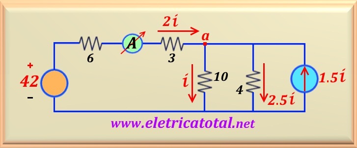
Figure 11-10.2
In order to determine the current flowing through the ammeter we will write the current equations for the
node a. Then:
A = i + 2.5 i - 1.5 i = 2 i
Now, we must calculate the value of i. To do so, just write the following mesh equation:
- 42 + 9 x (2 i) + 10 i = 0
And from there, we find the value of i, or:
28 i = 42 ⇒ i = 1.5 A
And how do we know A = 2 i, so:
A = 3 A
Power Balance
In the Figure 11-10.3 we see the complete circuit with the indication of the currents in the various components that form the circuit.
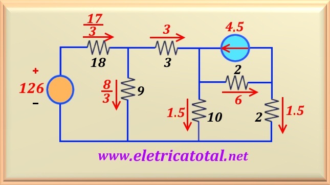
Figure 11-10.3
First, let us compute the dissipated powers on all resistors, or:
P18 = 18 x ( 17/3 )2 = 578 watts
P9 = 9 x ( 8/3)2 = 64 watts
P3 = 3 x 32 = 27 watts
P10 = 10 x ( 1.5 )2 = 22.5 watts
And the power dissipated by the two 2 ohms resistors, will be:
P2 = 2 x ( 62 + 1.52 ) = 76.5 watts
Adding all calculated powers will have the total power dissipated throughout the circuit. This power will be called
of P+. So:
P+ = 578 + 64 + 27 + 22.5 +76.5 = 768 watts
Now let's calculate the power supplied by the voltage sources. Powers provided
have negative values. The voltage on the dependent source is the voltage
drop on the resistor of 2 ohms
which is in parallel with it. Then, VS1 = 2 x 6 = 12 volts.
So, the power supplied will be:
PS1 = -12 x 4.5 = -54 watts
And the independent source provides a power of:
PS2 = -126 x (17/3) = -714 watts
Now, adding up the powers given and calling it P -, we have:
P - = - 54 - 714 = -768 watts
And as we know, the algebraic sum of the powers supplied and consumed by the circuit must be equal to
zero. Then:
∑ P = P+ + P - = 768 - 768 = 0 watt
And so, we find that the results are absolutely correct.