Problem 24-8
Source:
Adapted from Question 1 of the PUCRS II Electrical Circuits Test - 2019.
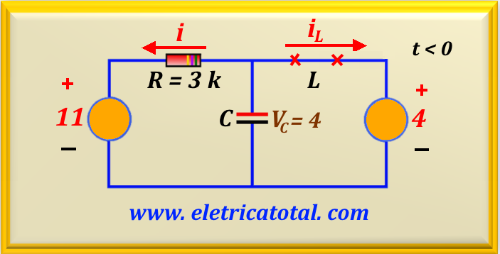
Determine the value of iL (t) to t > 0 knowing that the circuit is in steady state when the switch is in the position shown in Figure 24-08.1 for t < 0 .
Figure 24-08.1
Solution of the Problem 24-8
Item a
Note that for t < 0 we have the circuit shown in Figure 24-08.2, where we replace the inductor with a short circuit. With the current source and resistor
R1 we did a source transformation obtaining a voltage source of 11 volts in series with R1. Thus, we can add the values of R1 and R2, obtaining the value of R = 3 kΩ. Because the inductor behaves like a short circuit, we easily obtain the value of the voltage across the capacitor, that is,
Vc (0+) = 4 V. Following the indication of the currents according to the circuit, we obtain i (0+) = - (11 - 4) / 3 k = - 7/3 mA. And iL (0+) = (11 - 4) / 3 k = 7/3 mA, since no electric current flows through the capacitor .
These are the initial conditions of the problem.
Figure 24-08.2
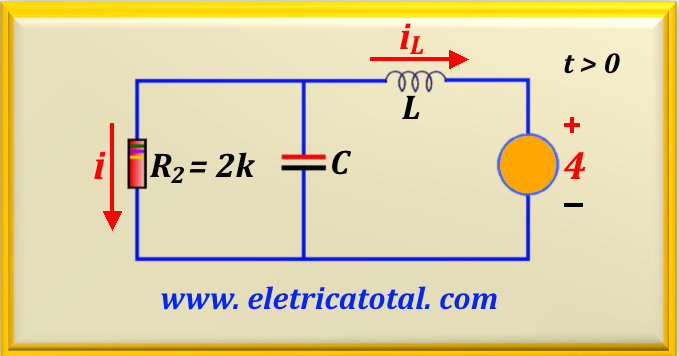
Para t > 0 a chave está na condição fechada. Como resultado, a fonte de corrente e o resistor R1 são eliminados do circuito e o resistor
R2 é colocado em paralelo com o capacitor, conforme mostra a Figura 24-08.3.
Figura 24-08.3
Thus, we have a parallel RLC circuit that is perfectly possible to be solved by applying the theory already studied.
Then, with the values provided by the problem, we can calculate the operating frequency of the circuit using eq. 24 - 06, we find:
ωo2 = 1 / L C = 1/ (6.25 x 10⁻⁶) = 160.000 rad2/s2
We easily conclude that:
ωo = 400 rad/s
Now let's calculate the value of α of a parallel RLC circuit. Using eq. 24-05, we have:
Note that in this case, α < ωo, confirming an underdamped response. Therefore, the two roots of the characteristic equation are complex and the solution equation will be in the form of eq. 24-14 and eq. 24-15.
Now we need to calculate the value of ωd, which is given by eq. 24-13. Then:
ωd = √ (4002 - 2502) = 312.25 rad/s
Then the system's response to iL (t) will be given by:
iL (t ) = iL (∞) + e- 250 t ( B1 cos (312.25 t) + B2 sen (312.25 t) )
From the circuits shown in the figures above, we have that iL (0+ ) = 7/3 mA and iL (∞ ) = - 2 mA. Therefore, for t = 0+
let's find the equation below.
As we know, sin 0 = 0, cos 0 = 1 and e0 = 1. So, the equation reduces to:
7/3 = - 2 + B1
Carrying out the calculation we find the value of B1, or:
B1 = 13/3
And to calculate the value of B2, we will use the initial condition vL (0+ ) = 0.
Since vL is related to the first derivative of iL, then deriving i L we find the relationship below:
d iL(0+) / dt =
vL(0+) / L =
- α B1 + ωd B2 = 0
Therefore, performing numerical substitution, we find:
250 . 13/3 = 312.25 . B2
Solving this equation, we find the value of B2, or:
B2 = 3.47
And now we can write the solution equation for the current in the inductor, or:
iL (t ) = - 2 + e- 250 t ( 13/3 cos (312.25 t) + 3.47 sen (312.25 t) )
Remember that the value of this current is in milliampere.