Problem + Hard 12-3 Source:
Problem 70 of the list of Electric Circuits I,
from the School of Engineering at UFRGS, Prof. doctor Valner Brusamarello.
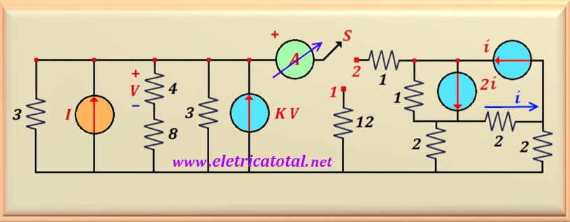
In the circuit of the Figure 12-03.1 , it is known that if switch S is in position 1, the ammeter
A shows a current of 5 A. If switch S is in position 2 then
the ammeter A shows a current of 14 A.
Find the values of I and K.
Figure 12-03.1
Solution of the Problem + Hard 12-3
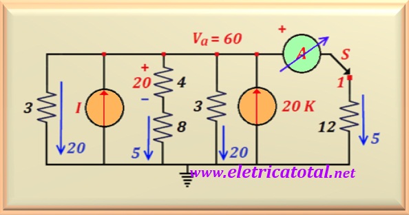
Initially, let's analyze the circuit when switch S is in position 1. For such,
let's redraw the circuit to better understand its operation. Never forget that an ammeter
ideal has an internal resistance equal to ZERO, so it acts like a short circuit and there is no drop
tension on it. See the Figure 12-03.2, the circuit redrawn at position 1 .
Figure 12-03.2
In position 1 the ammeter reads 5 A. So this current passing
across the 12 ohms resistor generates a voltage at point a of
Va = 60 volts. Knowing the voltage at point a
we can calculate the currents in all the resistors in the circuit. See in the picture
above, in blue, the values of the currents found by dividing the value of
60 volts by the value of each resistor. Note that the 4 ohms resistor flows a current
of 5 A and, as a consequence,
we find V = 20 volts. Now, using Kirchhoff's law
for node a we find:
I + 20 K = 20 + 5 + 20 + 5 = 50 A
That is, the two current sources together must provide a total of 50 A. From the first
information provided by the problem we get the equation above. To use the second piece of information, we must
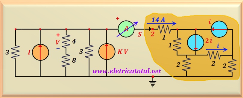
redraw the circuit as shown in the Figure 12-03.4.
Figure 12-03.4
Let's take a closer look at the part of the circuit highlighted in yellow. Note that we have two
current sources. Let's do an explosion of current sources. Look
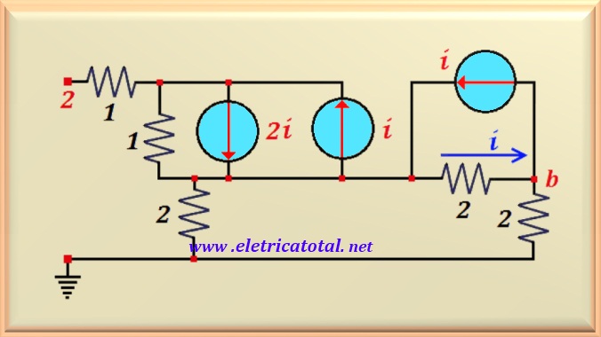
in Figure 12-03.5, how the part of the circuit highlighted in yellow turned out.
Figure 12-03.5
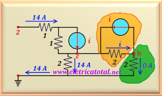
Note that we can associate the current sources in parallel. In the Figure 12-03.6, we
can see the final circuit with the currents indicated in blue.
Looking at the circuit highlighted in yellow, we see that using the law of
Kirchhoff for the node b, the current flowing through the resistor
highlighted in green equals ZERO.
Therefore, we can disregard the circuit highlighted in green.
Thus, point b is at the same level as ground.
Figure 12-03.6
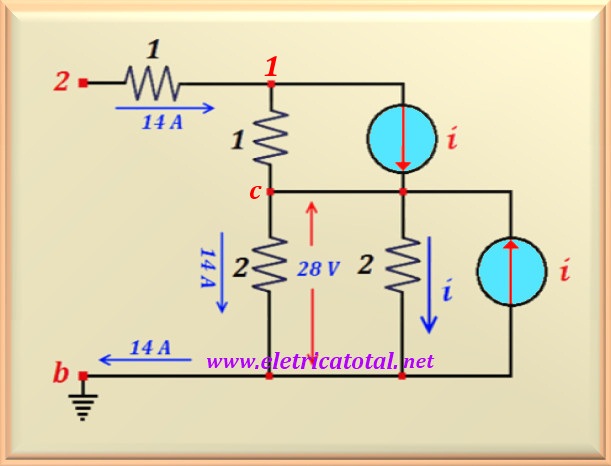
After these considerations, we can redraw the circuit as shown in Figure 12-03.7 .
Through the 2 ohms resistor, in which the current i flows (by definition
in the problem statement), and which is found
in parallel with the current source i, makes this current
be confined to these two components. Thus, the current of 14 A that leaves
of the circuit through point c, pass it all through the other resistor of 2 ohms,
causing a voltage drop of 2. 14 = 28 volts.
Note that this voltage is the same across the 2 ohms resistor where the
current i. Then, we can write:
2 i = 28 ⇒ i = 14 A
Figure 12-03.7
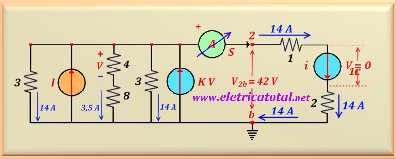
Thus, with the determination of the value of the current i, we realize that by the resistor
of 1 ohm that is in parallel with the current source i, at the top of the circuit,
no current passes because the 14 A that enters the
pin 2 will pass, all of it, through the current source i, nothing will pass
by the 1 ohm resistor. This indicates that the voltage drop across the
current source i that appears in the upper right part of the circuit, is V1 = ZERO.
Then, we can remove from the circuit the
1 ohm resistor, as well as the 2 ohm resistor and current source
i (which are in parallel), as they do not affect the operation of the circuit.
So, the circuit boils down to what appears in the Figure 12-03.8.
Figure 12-03.8
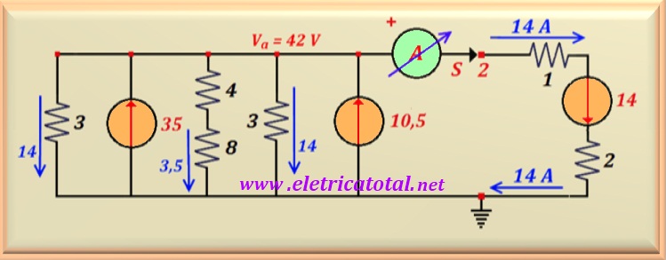
Adding all the currents indicated in the circuit by the blue arrows, arriving at
node b, we find the value
of 14 + 14 + 14 + 3.5 = 45.5 A. Furthermore, the voltage V across the resistor of
4 ohms is from 4 x 3.5 = 14 volts. Thus, the current source K V has the
value of 14K. Looking at the circuit, it is clear that the two current sources, I and KV, are responsible for
in providing the 45.5 A. Remembering that V = 14,
we can write the other equation we need to solve the problem, or:
I + 14 K = 45.5
Repeating the first equation here, we have a system of two equations with two unknowns.
I + 20 K = 50
Solving this system, one finds the values of the variables requested in the problem, that is:
K = 9 / 12 = 3 / 4
I = 35 A
Power Balance
Let's do a power balance.
See in the Figure 12-03.9, how the circuit was with the indication of the currents in the branches.
Figure 12-03.9
Let us, initially, calculate the powers dissipated in the resistors, remembering that,
by convention, we consider these powers POSITIVE.
P3 = 3 x 142 = + 588 watts
P3 = 3 x 142 = + 588 watts
P12 = 12 x 3.52 = + 147 watts
P1 = 1 x 142 = + 196 watts
P2 = 2 x 142 = + 392 watts
Adding all these values together, we find:
P+ = 588 + 588 + 147 + 196 + 392 = + 1,911 watts
Now, for the calculation of the powers in the sources, let's remember
that voltage sources with current flowing out of the positive pole are considered
NEGATIVE powers, as they are supplying power to the circuit. Otherwise
will be POSITIVE powers. The same goes for current sources.
PF35 = - 35 x 42 = - 1,470 watts
PF10,5 = - 10.5 x 42 = - 441 watts
The power supplied to the circuit is exclusively from the current sources.
P- = - 1,470 - 441 = - 1,911 watts
Finally, we know that the algebraic sum of the powers supplied and received
in a circuit must be equal to ZERO, that is:
PTotal = P+ + P- = + 1,911 - 1,911 = 0 watt
Note that we do not take into account the power of the current source
i = 14 A as the potential difference over it is zero. Soon,
the supplied or absorbed power is also zero. For current source i
in parallel with the 2 ohms resistor, we also do not calculate because the resistor
absorbs all power from the source.
Therefore, the circuit satisfies the law of knots and meshes, as well as
the power balance.