Problem + Hard 11-3 Source:
Problem 41 - List of
Electric Circuit exercises I - School of Engineering - UFRGS - 2011 - Prof.
doctor Valner Brusamarello.
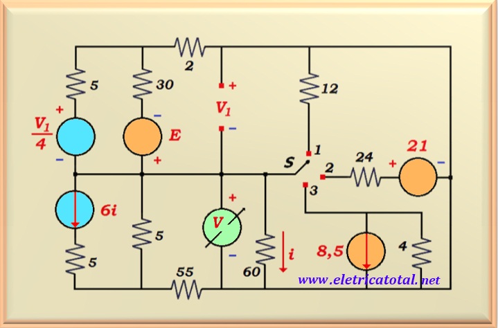
In the circuit of the Figure 11-03.1, when the switch "S" is in "position 1" the voltmeter indicates
the value of - 16 volts.
a) Determine the value of "E".
Determine the voltmeter reading:
b) When the switch "S" is in "position 2".
c) When the switch "S" is in "position 3".
Figure 11-03.1
Warning: The answer in the list of exercises has a typo. The value measured by the voltmeter,
at position 1, it was one of the data in the problem. For position 2, the "MINUS" sign was missing. Too many answers, Okay.
Solution of the Problem + Hard 11-3 -
Transf. of Sources
Item a
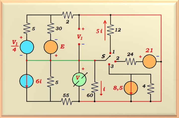
In the scheme below, it was emphasized through the red line and the green line,
the points that are connected. Removed value resistor
5 ohms that was in series
with the current source 6i, as it does not interfere with the results.
Notice that when switch S is in position 1, the resistors
of 60 ohms (through which the i current passes) and the 12 ohms,
are in parallel. Therefore, they are under the same potential difference. Soon,
if you pass i through 60 ohms, then 5 i will pass through
12 ohms resistor. Note the Figure 11-03.2.
Figure 11-03.2
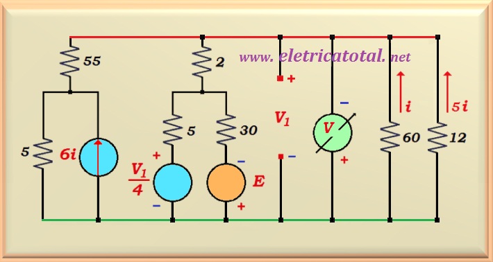
In possession of this information, and bearing in mind that the red line interconnects
all the elements connected to it, the circuit was redesigned to have a better view
more objective. Don't forget that the key S is at position 1.
Try to understand the changes that have been
carried out and conclude that the two circuits are absolutely identical, although with
different topologies, as shown in the Figure 11-03.3. Watch carefully
where the green and red lines were.
Figure 11-03.3
By making some source transformations, it is possible to further simplify the circuit.
With the current source 6i and the resistor of 5 ohms, calculate the
Thévenin equivalent.
The resistor of 5 ohms must be added to the resistor of 55 ohms
(since they will be in series) and a value of 60 ohms results. This resistor will
series with a voltage source of 30 i.
And doing a Norton results in a current source of 0.5 i
in parallel with the 60 ohms resistor. It is easy to see that this resistor
a current i will also circulate, since it is in parallel with the other
60 ohms resistor (right side of circuit). See the Figure 11-03.4 for
transformations carried out.
Figure 11-03.4
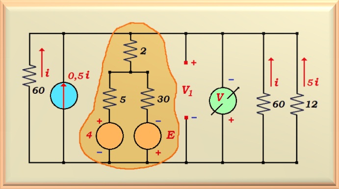
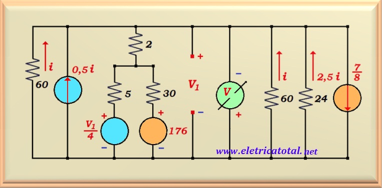
The circuit that appears highlighted in yellow in the Figure 11-03.4 can be simplified. Initially, V1 = +16
volts. Note that
V1 has the opposite polarity to V (voltage measured by the voltmeter). So the source
V1 / 4 can be replaced by a voltage source of 4 volts.
You must do the Norton of the two voltage sources with their respective
series resistors. Calculate the value of the equivalent resistance of the parallel circuit between
the resistors of 5 and 30 ohms and add the one of 2 ohms (since they are in series).
Thus, it is possible
simplify the entire circuit highlighted in yellow by a voltage source in series with
a resistor. See the Figure 11-03.5 for the simplified circuit. Note that the voltmeter does not pass current, because
this is considered an ideal instrument so it has infinite resistance.
Figure 11-03.5
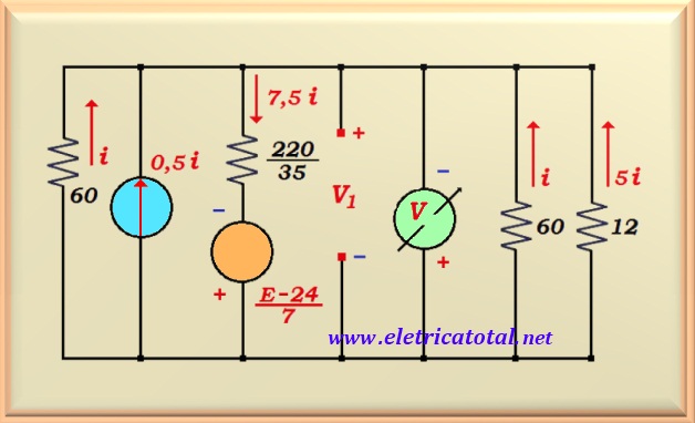
Note that the current of 7.5 i flowing through the circuit that was highlighted in yellow is the sum of all the currents that go up in the circuit, that is, 5i + i + i + 0.5i = 7.5i.
We know that V = - 16 volts so it's easy to calculate the
current value i, because:
i = V / 60 = - 16 / 60 = - 4 / 15 A
Making the mesh that encompasses the voltage source , resistor and V1,
find the equation that will allow you to calculate the value of E, that is:
- 16 + (220/35) (7,5) (- 4/15) - E/7 + 24/7 = 0
Carrying out the calculation we find the value of E, or:
E = - 176 Volts
Item b
To respond to item b, consider the same changes made
in item a, but replacing the 12 ohms resistor with a 21 Volts voltage source in series with a
resistor of 24 ohms, which is the case for switch "S" in position 2. It is very important to understand that when the switch "S" is in position 2, the reading of the voltmeter is unknown.
Figure 11-03.6
Making the Norton of the 21 volts source with the resistor
of 24 ohms, we are left with the circuit above. See we have a current source
7/8 amp (pointing down) in parallel with a
24 ohms resistor. From the data of the problem, it is known that in the resistor
of 60 ohms passes a current equal to i. So looking
looking closely at the circuit, it can be concluded that V1 = - 60 i. So, can you
replace the font V1 / 4 with 15 i, not forgetting that it must be inverted
the polarity of the source, because V1 = - 60 i.
It is also concluded that in
24 ohm resistor, which is in parallel with the 60 ohm resistor,
passes 2.5 i.
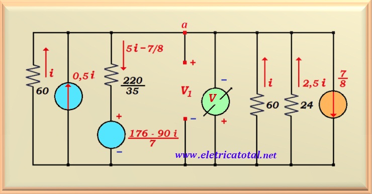
Therefore, by substituting these values in the circuit, the diagram of the Figure 11-03.7 is obtained.
Figure 11-03.7
Finally, work on the circuit highlighted in yellow and simplify it. See on
Figure 11-03.8 how the redesigned circuit looks like. Note that the current flowing down the
resistor of 220 / 35, is the result of the equation of node a (i + 0.5 i + i + 2.5 i - 7/8 = 5 i - 7/8).
Figure 11-03.8
Meshing V1 with the branch containing the voltage source
which depends on i, we can calculate the value of i, since V1
also depends on i. Thus, the following equation is found:
Therefore, solving the equation, we arrive at the value of i, or:
i = - 0,25 A
Now, remembering that V1 = - 60 i = 15 Volts and not
forgetting that the voltage measured by the voltmeter has the opposite polarity to
V1 (see note after problem statement), it is concluded that V
(value measured by the voltmeter) has the values of:
V = - 15 volts
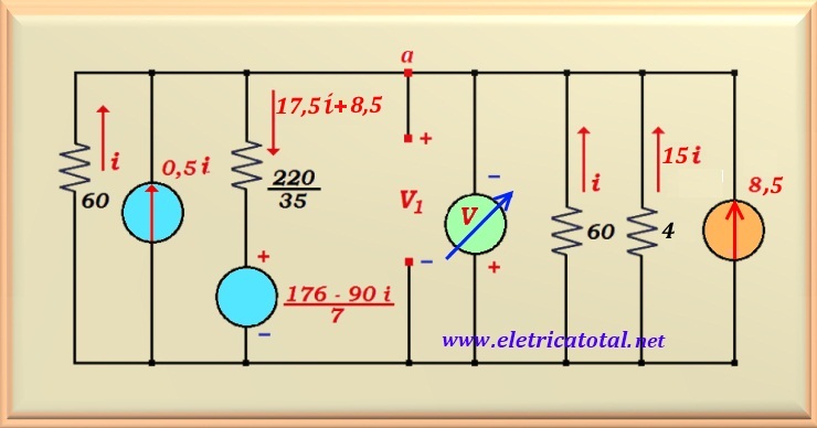
Item c
For item c the same considerations apply as for item b, emphasizing
that the voltage source in series with the resistor has been replaced by a current source
8.5 amps in parallel with a 4 ohm resistor. Also worth the relationship
V1 = - 60 i . Thus, the Figure 11-03.9 shows the circuit.
Figure 11-03.9
The process is the same as in item a. Making the mesh
V1 with the branch containing the voltage source
which depends on i, the value of i can be calculated, since V1 = - 60 i .
So, you have the following equation:
60 i + 110 i + 374/7 + 176/7 - (90/7) i = 0
Therefore, solving the equation, we obtain the value of i, or:
i = - 0,5 A
So, remembering that V1 = - 60 i = 30 Volts and not
forgetting that the voltage V, measured by the voltmeter, has the opposite polarity to
V1, it follows that V (value measured by the voltmeter) is equal to: