Problem 65-10
Source: Problem elaborated by the author of the site.
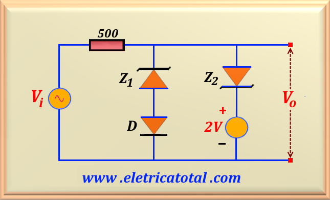
Given the circuit shown in the Figure 65-10.1, calculate the output voltage Vo, assuming that the input voltage is given by Vi = 15 sin t. Make a graph showing the output waveform. Consider the voltage on the conducting of the diode as VD = 0.7 V, VZ1 = 2.3 V e VZ2 = 3.0 V.
Solution of the Problem 65-10
The branch formed by the zener diode Z2 and the voltage source of 2 V will conduct with 0.7 + 2 = 2.7 V. Until the input voltage reaches this value, the output voltage is a copy of the input voltage. As soon as Vi, in its positive semi-cycle, reaches the value of
2.7 V this circuit will limit the output voltage to that value. In the positive semicycle, the other branch, formed by Z1 and D is totally inoperative since the output voltage will never reach the value of 2.3 + 0.7 = 3.0 V, which is required for conducting. So for the positive semicycle we can write:
And in the negative semicycle the branch formed by the zener diode Z2 and the voltage source of 2 V will go into conduction with - 3 + 2 = - 1.0 V. Until the input voltage reaches this value, the output voltage is a copy of the input voltage. Once Vi reaches this value the output voltage will be limited to -1.0 V. So for the negative semicycle we can write:
See Figure 65-10.2 for the waveform at the circuit output. It is noteworthy that the branch formed by Z1 and D is totally inoperative in both semicycles of the sinusoid. Thus, it is as if this circuit did not exist.


