Problem 58-1
Source: Problem elaborated by the author of the site.
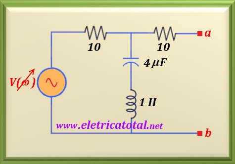
Calculate at what frequency the circuit shown in the Figure 58-1.1 will
have the lowest voltage value at the terminals a-b. Make a chart showing
the values in around the rejection frequency.
Solution of the Problem 58-1
This is an LC series circuit. The characteristic of this circuit is that when the capacitive reactance equals the inductive reactance the circuit is at resonance and results in a
null impedance between its ends.
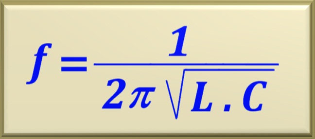
Recalling the equation that allows to relate the resonance frequency to the values of the inductor and capacitor.
Thus, substituting the numerical values, we find:
Then, for this frequency XL = XC and the resulting impedance will be
null. As a consequence, the voltage between the terminals a-b will also be zero. For any other frequency, other than f = 79.58 Hz, there will be in the
terminals a-b a voltage other than zero.
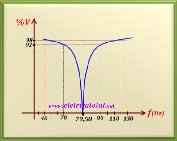
The graph in the Figure 58-1.2 shows how perfect the name of this circuit is, known as the circuit rejects band. Note that at the frequency where XL = XC,
that is, at the 79.58 Hz frequency, there is no signal at the output. For any other frequency other than this, signal is output. Notice how there is a fall on the output signal as it approaches the rejected frequency.
By didactic, no load was placed on the output of the circuit.


