Problem + Hard 3.1
Source: Problem 6.24 - page 216 - SADIKU, Matthew N. O. , ALEXANDER, Charles K. - Book: Fundamentals of Electric Circuits - McGraw Hill - 5th edition - 2013.
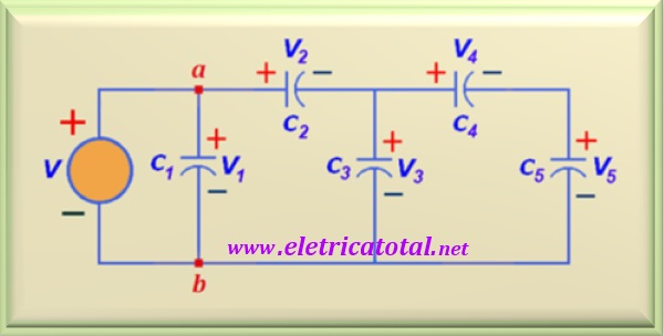
Knowing that
C1 = 30 µF , C2 = 60 µF , C3 = 14 µF ,
C4 = 20 µF , C5 = 80 µF , and V = 90 volts
a) Calculate the total capacitance of the circuit below, between points a and b;
b) Calculate the charge on each capacitor;
c) Calculate the voltage across each capacitor;
d) Calculate the accumulated energy in each capacitor.
Solution of the problem:
click here!
Problem + Hard 3.2
Source: Problem 6.23 - page 243 - IRWIN, J. David - Book: Circuit Analysis in Engineering - 4th edition - Ed. pearson - 2013.
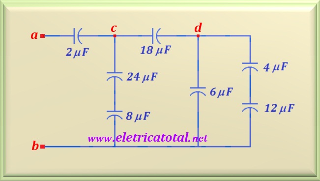
If the voltage at terminals a-b of the circuit in the figure below is 28 volts,
determine the voltage across each capacitor.
Solution of the problem:
click here!
Problem + Hard 3.3
Source: Problem 25-28 - pag 135 - HALLIDAY, RESNICK,
WALKER, Jearl - Book: Fundamentals of Physics - Vol 3 - Ed. LTC - 8th edition - 2009.
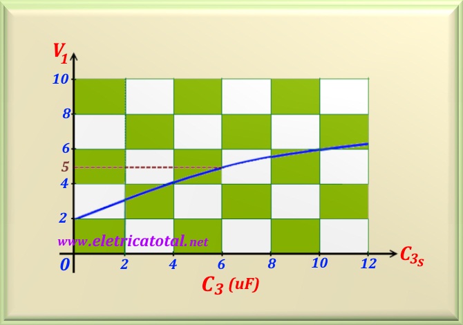
The capacitor C3 of the circuit in the figure below, on the left, is a capacitor whose capacitance can be varied. O
graph in the figure below, on the right, represents the electric potential V1 between the plates of the capacitor
C1 as a function of C3. For different values of C3 we have different values for
V1. We know that the electric potential V1 tends asymptotically to 10 volts when
C3 → ∞.
Determine:
a) The electric potential V of the source;
b) The values of C1 and C2.
Solution of the problem:
click here!


